PYRAMID PATIO HEATER Model# SRPH98 Instructions Manual DANGER If you smell gas: 1. Shut off gas to the appliance. 2. Extinguish any open flame. 3. If odor continues, keep away from the appliance and immediately call your gas supplier or fire department. DANGER Do not store or use gasoline or other flammable vapors and liquids in the vicinity of this or any other appliance. An LP-cylinder not connected for use shall not be stored in the vicinity of this or any other appliance.
WARNINGS AND CAUTIONS DANGER CARBON MONOXIDE HAZARD This appliance can produce carbon monoxide which has no odor. Using it in an enclosed space can kill you. Never use this appliance in an enclosed space such as a camper, tent or home. WARNING: Improper installation, adjustment, alteration, service r o maintenance can cause property damage, injury or death. Read the installation, operating and maintenance instructions thoroughly before installing or servicing this equipment.
WARNINGS AND CAUTIONS NOTE:PLEASE READ THE FOLLOWING SAFETY RULES WARNING: The installation must conform with local codes or, in the absence of local codes, with the National Fuel Gas Code, ANSI Z223.1/NFPA 54, NFPA58 Natural Gas and Propane Installation Code, CSA B149.1, or Propane Storage and Handling Code, B149.2 Any guard or other protective device removed for servicing the heater must be replaced prior to operating the heater. Installation and repair should be done by a qualified service person.
WARNINGS AND CAUTIONS NOTE:PLEASE READ THE FOLLOWING SAFETY RULES WARNING: Within a partial enclosure which includes an overhead cover and three side walls, as long as 30 percent or more of the horizontal periphery of the enclosure is permanently open. The pressure regulator and hose assembly supplied with the appliance must be used, replacement pressure regulators and hose assemblies must be those specified by the appliance manufacturer. This appliance requires 9kg(20lb) LP-gas supply cylinder.
WARNINGS AND CAUTIONS NOTE: PLEASE READ THE FOLLOWING SAFETY RULES: Perform a leak test with a soapy solution: 1. To check gas connections. 2. After connecting a new cylinder. 3. Upon re-assembly after disassembly. This heater is designed to operate with a standard 20 Ib propane cylinder with Approved Cylinder Connection.
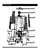
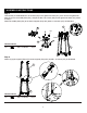
EXPLODED VIEW 6
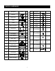
PARTS & HARDWARE Description AA M5 Wing Nut 3 BB M5 Stud 3 1 CC M5 x 12 Screw 68 Mesh 4 DD M5 Nut 3 4 Spiral 1 EE Guard Bracket 4 FF M5 Bolt 3 5 Burner Assembly 1 GG Handle 1 6 Back Panel 1 HH 4 7 Gas Cylinder Holder M4 x 25 Screw (pre-assembly) 1 8 Fire Damper 1 II M8 x 10 Screw (pre-assembly) 3 9 Upper Support 4 JJ M8 Nut (pre-assembly) 3 10 Glass Tube 1 11 Glass Tube Base 1 KK 8.
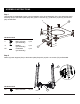
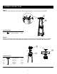
ASSEMBLY INSTRUCTIONS Step 1 Unscrew the pre-assembled screws, nuts and washers on the wheel assembly (#17), then attach the wheel assembly (#17) to the bottom plate (#16) with (3) M8 x 10 screws (II), (3) M8 nuts (JJ) and (3) 8.5 washers (KK) as illustrated. II 16 Hardware Used II M8 x 10 Screw (pre-assembly) 3 pcs JJ M8 Nut (pre-assembly) 8.
ASSEMBLY INSTRUCTIONS Step 3 Unscrew the pre-assembled M4 x 25 screws (HH) on the glass tube base (#11), then remove the glass tube base (#11) from the middle plate (#12), and put the M4 x 25 screws (HH) and the glass tube base (#11) aside for Step 7. Attach the middle plate (#12) to the lower supports (#13) with (8) M5 x 12 screws (CC) as illustrated.
ASSEMBLY INSTRUCTIONS Step 5 Attach the upper plate (#2) to the upper supports (#9) with (8) M5 x 12 screws (CC) as illustrated. 2 CC 9 Hardware Used CC M5 x 12 Screw 8 pcs Step 6 Attach the fire damper (#8) to the upper plate (#2) with (3) M5 bolts (FF) and (3) M5 nuts (DD), then attach the reflector (#1) to the fire damper (#8) with (3) M5 wing nuts (AA) and (3) M5 studs (BB) as illustrated. 8 1. 2.
ASSEMBLY INSTRUCTIONS Step 7 Attach the glass tube base (#11) to the middle plate (#12) with (4) M4 x 25 screws (HH) as illustrated. HH 11 12 Hardware Used HH M4 x 25 Screw (pre-assembly) 4 pcs Step 8 Attach the spiral (#4) to the burner assembly (#5) with (2) M5 x 12 screws (CC), then attach the burner assembly (#5) to the middle plate (#12) with (4) M5 x 12 screws (CC) as illustrated.
ASSEMBLY INSTRUCTIONS Step 9 Attach the gas cylinder holder (#7) to the back panel (#6) with (2) M5 x 12 screws (CC) as illustrated 6 CC Hardware Used CC M5 x 12 Screw 7 2 pcs Step 10 Attach the back panel (#6), left and right panel (#14) to the lower supports (#13) with (12) M5 x 12 screws (CC) as illustrated.
ASSEMBLY INSTRUCTIONS Step 11 Place the glass tube (#10) by guiding it up to insert the upper end through the center hole in the upper plate. Do not force the tube. Slide the bottom end into place and settle it into the hole in the glass tube base. Ensure that the Glass Tube is positioned properly to cover the spiral. 10 Step 12 Attach (4) meshes (#3) to the upper supports with (4) M5 x 12 screws (CC) and (4) guard brackets (EE) as illustrated.
ASSEMBLY INSTRUCTIONS Step 13 Unscrew the pre-assembled M4 x 10 screw (LL) on the handle (GG), then attach the handle (GG) to the front panel (#15) with M4 x 10 screw (LL). Install the front panel (#15) by inserting the two tabs at the bottom into the holes on the front of the bottom plate (#16). Attach the chain between inside of the door handle and the front of the burner assembly, then close the panel. The panel secures with magnet.
ASSEMBLY INSTRUCTIONS Step 14 When installing an LPG cylinder, it may be easier to remove the Front Panel completely and set aside. Place the cylinder on the Bottom Plate. Connect the gas hose to 20lb LPG cylinder (not included). Screw the regulator to the cylinder as illustrated. Tighten securely with the Fastening Belt. NOTE: The regulator with gas hose is supplied.
SAFETY CHECK WARNING : ONLY AN AUTHORIZED GAS TECHNICIAN SHOULD INSTALL THIS PRODUCT. Check for leaks All connection on the patio heater have been checked for leakage at the factory. Follow these steps to check the gas hose/regulator/cylinder connections: brush P3 P1 P2 1) Make leakage solution by mixing 1 part liquid dish soap and 3 parts water. 2) Spoon or brush several drops (or use squirt bottle) of the solution onto hose connection, regulator & cylinder connection. 3) Turn on gas cylinder valve.
WARNING: DO NOT ATTEMPT TO OPERATE THE APPLIANCE UNTIL YOU HAVE READ AND UNDERSTAND ALL PRECAUTIONS. FAILURE TO DO SO CAN RESULT IN PROPERTY DAMAGE, SERIOUS INJURY, OR DEATH. Unscrew the cap of the igniter placed on the control box and insert the included AAA battery with the POSITIVE end facing out.
OPERATION OFF H HIG 1. Make sure control knob is in the “OFF” position. 2. Turn LP cylinder gas valve to fully open position. 3. Push in control knob and turn counter-clockwise to "IGNITE" position, at the same time push in the ignition button and keep the control knob depressing until lighting the burner. 4. If the burner is lit,keep press down the ignition button for 30 seconds before releasing control knob. 5.
LOCATION SAFETY INFORMATION Minimum clearance from combustible surfaces 36'' This heater is primarily used for the heating of outdoor patios, decks, spas, pools and open working areas. Combustible materials are considered to be wood, compressed parter, plant fibres, plastic or other materials that are capable of being ignited and burned. Always make sure that adequate fresh air ventilation is provided. Follow the spacing tolerances shown in the following figure right at all times.
MAINTENANCE/STORAGE CLEANING AND MAINTENANCE : To enjoy years of outstanding performance from your heater make sure you perform the following maintenance activities on a regular basis: Keep exterior surfaces clean. Use warm soapy water for cleaning. Never use flammable of corrosive cleaning agents. While washing your unit, be sure to keep the area around the burner and pilot assembly dry at all times. If the gas control is exposed to water in any way, do NOT try to use it. It must be replaced.
MAINTENANCE/STORAGE Spiders and insects can nest in burner or orifices. This dangerous condition can damage heater and render it unsafe for use. Clean burner holes by using a heavy-duty pipe cleaner. Compressed air may help clear away smaller particles. Carbon deposits may create a fire hazard. Clean dome and burner screen with warm soapy water if any carbon deposits develop. STORAGE: Between uses: Turn the control knob to "OFF" position. Turn LP cylinder to "OFF" position.
PROBLEM POSSIBLE CAUSE CORRECTIVE ACTION Cylinder valve is closed Open valve Blockage in orifice or pilot tube Pilot won’t light Air in gas line Note: Heater operates Low gas pressure with cylinder valve at reduced efficiency fully open below 40ºF (5ºC) Igniter fails Pilot won’t stay lit Burner won’t light Burner flame is low Clean or replace orifice or pilot tube Open gas line and bleed it (pressing control knob in) for not more than 1 - 2 minutes or until you smell gas Turn cylinder valve OFF
ONE-YEAR LIMITED WARRANTY The appliance has been manufactured under the highest standards of quality and workmanship. We warrant to the original consumer purchaser that all aspects of this product will be free of defects in material and workmanship for one (1) year from the date of purchase. A replacement for any defective part will be supplied free of charge for installation by the consumer. Defects or damage caused by the use of other than genuine parts are not covered by this warranty.