Heath Data Recorder HDR Series User’s Manual & Field Installation Guide Heath Consultants Incorporated Houston, TX 713-844-1300 Fax: 713-844-1309 1-800-HEATH-US www.heathus.
HDR Series HDR User’s Manual & Field Installation Guide Proprietary Notice The contents of this manual are proprietary to Heath Consultants Incorporated. Reproduction of this manual, in whole or in part, is prohibited without the express written consent of Heath Consultants Incorporated. Heath Consultants Incorporated operates under a continual product improvement program and reserves the right to make improvements and/or changes without prior notification.
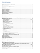
Table of Contents HDR I.S. Series (Purpose of this manual) ....................................................................................... 2 Table of Contents ............................................................................................................................ 3 Heath Data Recorder (HDR) Overview .......................................................................................... 4 HDR Features .............................................................................
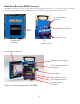
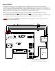
Heath Data Recorder (HDR) Overview The HDR is a microprocessor based, self-contained system designed for the purpose of process monitoring using integral pressures and temperatures. Figures 1 illustrates the location of major components and user interface items. Temperature probe Ports 1 & 2 External Modem cable Port LCD Display 1 2 3 Pressure Ports 1, 2, 3 Scroll Button (on bottom) RS232 PC Comm.
HDR Features • Handles up to three pressures (3) and two (2) temperatures (plus ambient). • Intrinsically safe: Class I Div I Group D (without internal modem). • Measures, records & alarms on all connected sensors every second. • Single Alkaline “D” battery provides power for up to 4 years. • Single Lithium “AA” Backup battery will provide 100% operation for up to 1 year after main battery is depleted. • Wall mount, Pipe mount and Portable configuration options.
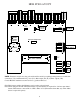
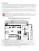
PRESS 1 J6 J5 J7 WIRED TO DISPLAY BUTTON JP5* 123 DATA MEMORY BATTERY BACKUP J2 GND GAS TEMP PROBE #1 PRESS 2 P1 +E P1 +S P1 -E P1 -S GND J10 PRESS 3 P2 +E P2 +S P2 -E P2 -S GND J11 DIRECT COM 1 P3 +E P3 +S P3 -E P3 -S GND J14 PULSE OUT B GND PULSE OUT A GND GND PULSE INPUT J13 MODEM COM 2 GND TXD RXD CTS RTS CD TXM RXM GND HDR PCB LAYOUT J9 GAS TEMP PROBE #2 GND GAS TEMP 2 J8 ASSY#: 77R65-9320 REV F GND INDEX B STOBE INDEX A STOBE 3V SYS 3V CR2032 INDEX INPUT (HVC ONLY) J12 BA
Mounting & Installation Housing Configuration The HDR is available in many configurations.
Battery Pack and Back-up Batteries The HDR units utilize (1) 1.5-volt, encapsulated “D” cell alkaline battery as its primary power source. The pack supplied with the HDR consists of an alkaline dry cell and a protection circuit. (Part number(s) on page 42) NOTE: This battery is not rechargeable. HDR units are shipped from the factory powered and ready to install in the field (unless otherwise specified). The HDR incorporates an on board uninterruptible power supply.
External Modem The HDR is equipped with two RS232 communication ports. The Direct Port is dedicated to local direct PC communication at 19200 baud using the HDR com cable. The Remote Port is used for connecting a modem. Remote baud rates available are 300, 1200, 2400 (default), 4800, 9600 and 19200. When configuring for a remote modem, the “Remote Modem Baud Rate” in the unit must match the baud rate of the field modem being used. Connect the RX, TX & GND from the modem to the instrument on J13.
Internal Modem The HDR may be equipped with an internal modem and phone line surge suppressor. The modem is pre-configured and pre-wired from the factory, ready for remote communication. If the HDR is equipped with the phone line suppressor, it will be connected directly into the modem’s RJ-11 connector. A 12-volt battery pack (8 “AA” batteries) is supplied, but not connected when shipped. The user must connect prior to remote communication.
HDR Host Operating Software HDR Host is the companion software interface to the HDR instrument. The application program provides for configuration, calibration, local and remote communication, interrogation, data collection and data processing. The program is supplied on CD ROM media. The self expanding executable “setup” file will guide the user through the installation process. This install will work in Windows operating systems for Win XP, Win Vista, Win 7 & Win 8.
Accept the agreement. Then click “Next” to continue. Click “Next” to continue or change the default location of the HDR Host data files.
Click “Next” to continue or change the default location of the data log files. Click “Next” to continue or change the default location of the HDR Host shortcut.
Select additional icons. Click “Next” to continue. Click “Next” to continue installation.
Click “Finish” to complete the installation. Select the box to view the “README.TXT” file. Quick Start Guide 1. Run “HDR Host Setup 4.02.exe” to install the HDR Host software from the CD software disk provided. 2. After first time running of the software- message: Verify PC time is correct (“Check” to remove if needed or leave to remind). a. Setup “Host Setup” (Com 1, 19200, Direct, is most common).
HDR Configuration- Detailed User Friendly Names (Allows custom channel names of active channels- when required) 1. Go to the Configure Column/ “User Friendly Names” 2. Click the check-box next to the channel to add or type a custom name for the channel. Note: This custom name will follow the channel throughout the software & reports. Site info and Instrument Modem 1. Enter Site Address info. Note: Site address line #1 will be used to create filenames for downloaded reports. 2.
Pulse outputs 1. The HDR has two pulse outputs that can be independently configured for Alarm closure (for external visual or audible alert or to notify another device of the alarm) or pulse repeating. To set up the pulse outputs for alarm pulse closure: a. Go to the Configure column. b. Select “Configure user friendly names”. c. Select the pulse output to activate, click “OK”. d. Then go to the configure column/ “Configure Pulse I/O and 4-20 Ma Sender”. e.
Alarms Configuration (set up to 16 alarms as necessary): 1. 2. 3. 4. 5. 6. 7. 8. 9. 10. Click the box next to the alarm to activate Type the “Name” of the alarm to configure (use any name to describe this alarm). Select the “Point” (P1,P2,P3,T1,T2,Case Temp, Batt Volt, Lith volt) to monitor. Select “H/L” (Lo, Hi, Dlt). Lo= Low pressure alarm/ Hi= High press alarm/ Dlt= Delta (difference from one read to another in a 1 second period either high or low). Select the “Mode” (Auto/Manual).
Configure LCD sequence 1. Go to the configure column/ “LCD Display Sequence”. Select the items to be viewed on the HDR LCD screen. Leave any items un-checked to hide them from the LCD. In the example below, if “Low Press 1” alarm was active, the low pressure alarm would not be visible on the LCD (because it’s unchecked) but will show in the software. The HDR has 3 types of data logs: 1. Profiler: (Core log) is programmable from 1 min up till 60 min interval.
2. Watch log: Records 1 pressure channel (High resolution log selectable from 1 second data, for 9 hours data storage, up to 16 second averaged data to provide 6 days of stored data). This log is circular- first data in last data out. To save this data go to “Display column”/ “View Watchlog”/ Select the timeframe & start time, click OK. The data will appear automatically in Excel. This is probably the best log to use for leak testing. 3.
Set Access Control (This sets the security passwords of the instrument) 1. In HDR Host, Go to the Configure Column/ “Set Access Control” in the instrument. Note: “logon” and “readonly” are the instrument’s defaulted passwords. These can be changed to be more secure. 2. The “Host Setup” screen (See below) allows setting up the password in the computer. When the “Host” password matches the “instrument” password, access is granted & no password will be prompted.
Auto Configure (Allows saving and sending the Configuration, Calibration, Transducer Poly & site info) 1. To Save this file a. Go to "Configure column/ Auto Configure/ & click: “Save Inst Config, Cal & Polys" b. Click “Save” Or type a custom filename & click “Save”. 2. To send (restore) this file to the instrument: a. Go to "Configure column/ Auto Configure/ “Send Config, Cal & Polys to Inst" b. Select the configuration file: Example: "325012345.cfg" c.
Modbus Implementation 1. Modbus can be used as long as it is ACSII (Modbus RTU is not currently active) Packet framing: Data bits=7 / Parity= Even/Odd/None / Stop bit=1. Note 1: After setting Modbus to ASCII, the remote port will not work using the Native protocol Sandia. Note 2: The direct port will always work with Sandia protocol (native). 2. Set up Modbus in the “Configure” column/ “Site Info” a. Baud rate should match the baud rate of the modem connected to the remote port of the instrument. b.
Configuring for use with an IP modem 1. Select “Host Setup – Configure Host”. 2. Click the “Network” Port Selection and then click “OK”.
3. Select “Comm – Master Directory”. 4. Click on the “New IP Addr” button.
5. Enter the IP address, Port Number and choose a Name/Location for the installation. In the COM Selection drop-down box, click on “Select 4 – TCP/IP” and then click “OK”. Click “OK” back on the Master Dialing Directory window to accept the information. The screen shown below is an example using the Heath engineering HDR instrument. 6. To begin using the IP modem it must be wired correctly, configured properly and powered up. The HDR modem port baud rate must match the IP modem baud rate.
8. Double-click the IP modem’s site name or single click the site name and then click “OK”. Editing is also available with this screen if needed. 9. While connecting to the IP modem a status window will appear. The IP address and Port shown below are an example only. The actual values will differ.
10. Once connected, the Host screen will indicate the connected IP address in yellow at the bottom of the window. 11. Select “Security – Logon Instrument” to logon to the remote HDR. When successful, “Logged ON” will be indicated in green at the bottom of the window. NOTE: Please be patient while logging onto the remote HDR. It can take several seconds to logon due to network traffic and delays.
12. To illustrate remote IP modem communication, select “Display – Display 1 Live Readings”. 13. The Live Readings window will appear after the data has been gathered and communicated. Note: This screen updates each second.
14. Remote HDR IP modem communications are available for use using the HDR Host. When finished, exit remote IP modem communications by selecting “Comm – Network – End Session”. The remote HDR will be logged off and the network session will end.
HDR 325 Profiler Memory Capacity Table Example: 10 min recording of 4 fields yields 350 days of Profiler data stored in the HDR The Profiler is selectable from 1 min. up to 60 mins & a total of up to 22 recordable fields. The Profiler can record all of the following: Pressure 1,2,3 (Ave, Min, Max)/ Temp 1 & 2 (Ave, Min, Max)/ Ambient Temp (Ave, Min, Max)/ Ave. Main Battery voltage/ Pulse Input counts.
HDR Firmware Update Procedure (This update will not delete any Cal, CFG or saved data) To get the firmware file, contact Heath Consultants Inc. tech support. Go to the “Tools” column / Select: “Update Instrument Program”. At the “Warning” screen, select “YES”. Enter YOUR User Name (Min 3 digits/ Your initials or first name will work). Select “Load” (Do not change the selection- “Firmware W/O Cfg & Cal”).This will save ALL Calibration. Select the “Hex” file: (MeterHexHDR403.a43).
#3 Enter YOUR name here Select this to save Cal & CFG Select this to default Cal & CFG #4 #5 Same #6 33
#7 Watch & wait Active during update Programming firmware Successful #8 Select Cold Start to clear all logs 34 #9 Exit to normal operation
#10 Reset Date & Time #10 Reset Date & Time New Firmware should look like this in “Display/ View firmware”.
HDR Specifications Functionality Profiler Data Recording: Circular log: Large memory, recording intervals include: 1 min., 5 min., 10 min., 15 min., 30 min., 60 min. Records Min/Max/Ave Press 1,2,3, Min/Max/Ave Temp 1&2, Min/Max/Ave Ambient Temp & Batt volts Watch Log: Provides an additional high resolution circular pressure data log. Recording options are: logging data every second for 9 hours of memory storage or averaging 2 second data for 18 hours or 4 second ave. for 36 hours or 8 second ave.
HDR Maintenance and Troubleshooting The following may serve as a quick troubleshooting guide if you encounter problems in operating the HDR Heath Data Recorder. If any of these hints fail, call factory for assistance: Symptom Will not log on Diagnosis • Verify that proper com port is selected in HDR Host/ “Host Setup”.
When calling the factory or your area representative for further troubleshooting, please have the following information ready: Customer Information 1. Name(s) 2. Company 3. Phone Number(s) 4. Location (site I.D.) Hardware Information 1. Model of Instrument 2. Instrument Firmware Version 3. Battery Voltage 4. Instrument Serial Number 5. Date of Manufacture 6. Transducer Serial Number(s) (If Applicable) 7. Any externally connected devices 8. Phone Number (If Applicable) 9.
Maintenance Procedures Note: During the calibration process the last read pressure and gas temp will be used (LCD shows “- - CAL- -“) to calculate Corrected volumes, therefore it’s recommended to get into the calibration mode BEFORE removing the live pressure (or live gas temp) so the profiler will not record the pressure drop of removing the live pressure or removing the live temp from the gas line. Pressure Calibration: 1. 2. 3. 4. 5. 6. 7. 8. 9. 10. 11. 12. 13. 14. 15. 16. 17. 18. 19.
Back-up Battery Replacement Procedure This procedure describes how to replace the lithium back-up battery BT1 (HPN 77R65-8001) and the profiler back-up coin cell battery BT2 (HPN 77R65-8002). It is recommended to replace both batteries at the same time. If configured, the instrument will alert the user of a low lithium back-up battery on the LCD and via being connected to the instrument either by direct RS-232 or modem.
7. Install the retainer clip over the lithium battery and verify both latches seat properly onto the holder. Replace the CR2032 coin cell back-up battery per the following: Warning – make sure the main battery voltage is at least 1.2 V dc! 1. Locate BT2 in the lower left corner of the PCB. 2. Insert a small, thin bladed screwdriver into the gap on the left side of the battery and gently pry the left side up. 3. Remove the old battery.
Spare Parts & Accessories Pressure Transducer The HDR may be equipped with a wide variety of ranges, most of which are available in either gauge or absolute. Temperature Probe Temperature Probes are normally supplied with six-foot l o ng metal sheathed cable. Contact factory for nonstandard lengths. The temperature probe is HPN 77R91-1035. Modem (Internal Modem Assembly Retro Kit Part #77R61-9360) Contact the factory for other configurations.
Service Information: Warranties and Warranty Repair The HDR is warranted to be free from defects in material and workmanship for four (4) years from date of shipment (exclusive of the batteries). The warranty on authorized repairs in the Houston Factory Service Center (FSC) is ninety (90) days for materials and labor. This repair warranty does not extend any other applicable warranties. Our warranty covers only failures due to defects in materials or workmanship.
Configuration Worksheet Complete this worksheet prior to leaving the meter shop to facilitate field configuration and documentation. Always remember to download the IOR Snapshot or Configuration Log reports as a record of instrument configuration.
Technical Support 1-800-HEATHUS (1-800-432-8487) Heath Consultants Incorporated Factory Service Center 9030 Monroe Road Houston, Texas 77061 Phone: (713) 844-1350 Fax: (713) 844-1398 Heath Consultants Incorporated operates under a continual product improvement program and reserves the right to make improvements and/or changes without prior notification. Heath Consultants Incorporated 9030 Monroe Rd. Houston, TX. 77061 1-800-HEATHUS Fax: (713) 844-1398 www.heathus.