
Instruction Manual


Kompensator Installation
2 of 8
Ordering Chart
Kompensator | Product Code
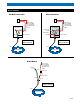
Example: KHL123 – 040 – CS
Cord-Set Type
CS Cord connected (No GFCI)
Length of Heater
5 to 40 feet 12 volt 3 watt per foot systems
5 to 30 feet 12 volt 5 watt per foot systems
5 to 60 feet 24 volt 3 watt per foot systems
5 to 40 feet 24 volt 5 watt per foot systems
Product
KHL123 12 volt 3 watt per foot
KHL125 12 volt 5 watt per foot
KHL243 24 volt 3 watt per foot
KHL245 24 volt 5 watt per foot
Notes: It is the requirement of the installer to provide proper voltage regulation and over-current protection.
It is also the recommendation of Heat-Line that since the power consumption of the product can never
be 0 to install a shut-off switch to prevent the draining of batteries or power supply.
General Requirements For Pipe Freeze Protection
• Kompensator heating cables may be used on metal and plastic water
pipes. Please consult Heat-Line if you have other pipes or tubing.
• Kompensator heating cables are not intended for use inside any
pipes, for freeze protection of liquids other than water, or for use in
classified hazardous locations.
• Install with a minimum of 1/2" fire-resistant, waterproof thermal insulation.
• Never use on any pipes that may exceed 150°F (65°C).
• Use appropriate wire gauge for the heating cables circuitry.
• Install only in accessible locations; do not install behind walls or
where the cable would be hidden.
• Do not run the heating cable through walls, ceilings, or floors.
• Connect only to circuits with the appropriate over current protection
and proper grounding and are protected from rain and other water.
Important: For the Heat-Line warranty to be valid, you must comply
with all the requirements outlined in these guidelines. Determine
Which Kompensator Heating Cable You Need for Pipe Freeze
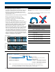
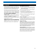
Protection Use the Tables 1 and 2 to select the correct heating cable.
Add 2 foot to your pipe length for each valve or spigot on your pipe
system. The charts assume the lowest outside temperature is 0°F
(-18°C), with a minimum of 1/2" thick waterproof, fire-resistant ther-
mal insulation (preformed foam). For protection to -20°F (-29°C), use
1" thick insulation. Important: All thermal and design information pro-
vided here is based upon a "standard" installation with heating cable
fastened to an insulated pipe. For any other application or method of
installation, consult Heat-Line at (800) 584-4994.
Pipe length (ft)
0
1/2
1
1 1/2
2
2 1/2
10 20 30 40 50 60
Pipe diameter (in)
Table 1 Metal Pipes
0 10 20 30 40 50 60
Pipe length (ft)
1/2
1
1 1/2
2
2 1/2
Pipe diameter (in)
Table 2 Plastic Pipes
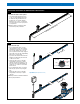
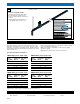
Bending the Cable
When positioning the heating cable on the pipe, do not bend tighter than
1/2" radius.
The heating cable does not bend well on a flat plane. Do not force such a
bend as heating cable may be damaged.
Optional Accessories
KHL-STAT Low voltage thermostat
PLD-CG Cable guards (package of 4)
INSUL-PAD Elastomeric flexible closed-cell insulation, 1/2" (12.5mm)
thick, 6" (152mm) wide, 10' (3m) long
INSUL-FOIL Aluminum reflective metalized foil bubble insulation
FOIL-TAPE Professional grade all weather foil tape 2.83" x 150'
(72mm x 46m)
INSUL-1.00 Closed cell polyethylene insulation sleeve for 1" ID pipe
(6' long, 1 5/8" ID, ¾" thick wall)
INSUL-1.25 Closed cell polyethylene insulation sleeve for 1 1/4" ID pipe
(6' long, 1 7/8" ID, ¾" thick wall)
INSUL-2.00 Closed cell polyethylene insulation sleeve for 2" ID pipe
(6' long, 2 5/8" ID, ¾" thick wall)
HLP-TAPE Black polyethylene insulation tape 2" x 100' (51 mm x 30 m)
INSUL-LABEL Electric Heat Trace Caution Label for Insulation
1/2"
Pre-Installation Information