
User Guide


9
2. Measure the liquid refrigerant temperature (in
Fahrenheit) at the service valve.
3. Determine the required liquid refrigerant pressure. Refer
to Tables 3-9 (pages 11-13) and Figures 5-11 (pages
13-16).
• IfthepressuremeasuredinStep1isgreaterthan
the required liquid refrigerant pressure determined in
Step 3, then there is too much charge in the system.
Remove refrigerant and repeat Steps 1 through 3
until the system is correctly charged.
• IfthepressuremeasuredinStep1islessthanthe
required liquid refrigerant pressure determined in
Step 3, there is too little charge in the system. Add
refrigerant and repeat Steps 1 through 3 until the
system is correctly charged.
Application Notes for using the Charging
Charts
• This equipment’s cooling system contains
refrigerant under high pressure. Always use safe
and environmentally sound methods when handling
refrigerant handling or servicing the unit. Review
the factory literature and safety warnings prior to
servicing.
• Whenrepairingsystemleaks,alwaysuseanitrogen
(inert) gas to protect the refrigerant system and pressure
check the repair before re-charging. Always replace
the filter-dryers when performing any repair to the
refrigeration system with one capable of acid removal.
After completing the repairs, evacuate the system to
350 - 500 microns and weigh in the refrigerant to the
amount specified on the unit rating label.
• Chargingchartsarevalidforavarietyofindoor,return
air conditions and are most influenced by the outdoor
ambient temperature, outdoor fan operation and the
unit operating voltage. Before using these charts, make
sure the unit is in a stable operating mode. As shown
in the charging charts (Figures 5 - 11, pages 13 - 16),
the ideal system sub-cooling can vary over the range of
operation. Reference the charts to determine the ideal
amount of sub-cooling for a given liquid pressure. Units
charged to other values will not perform at the rated unit
efficiency (EER) or rated Coefficient of Performance
(COP) in heating mode.
• To inspect a systems operation using quality
instruments, match the measured liquid temperature to
the units chart. The measured liquid pressure reading
should be within 3% of the charts value for most
installations.
• Forsystemsthatareoperatingwithmorethana5%
deviation, inspect the unit for the proper voltage and
phase balance and the refrigeration system for leaks.
• Unitsthatareoperatingatlessthen95%ofthenominal
voltage or with a 2% phase imbalance may see a more
significant deviation than the amount stated above.
• DO NOT use the charts in systems that have a fan cycling
under low-ambient control. Refer to the low-ambient kit
instructions for more information. (If applicable)
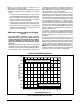
COOLING CHARGING CHARTS
Figure 3. Charging Chart for 2 Ton Units
250
275
300
325
350
375
400
425
450
475
70 75 80 85 90 95 100105 110 115 120 125
Liquid Temperature (° F)
Liquid Pressure (psig)
Remove refrigerant when above curve
Add refrigerant when below curve