
User Guide


8
• A high-pressure switch is factory installed and located
internally on the compressor discharge line of the outdoor
unit. If the discharge pressure rises above 650 psig,
theswitchwillopenandde-energizetheoutdoorunit.
The switch will close again after the discharge pressure
decreases to 460 psig. NOTE: When the switch opens
and then closes, there will be a 3 minute short cycling
delaybeforetheoutdoorunitwillenergize.Undernormal
conditions the switch is closed
• A low-pressure switch is factory installed and located
internally on the suction line of the outdoor unit. The
switch is designed to protect the compressor from a
loss of charge by interrupting the thermostat inputs to
the unit.
NOTE: If the suction pressure falls below 5 psig, the switch
willopenandde-energizetheoutdoorunit.Theswitchwill
close again when the suction pressure increases above
20 psig. When the switch opens and then closes, there is
a 3 minute short cycling delay before the outdoor unit will
energize.Undernormalconditionstheswitchisclosed.
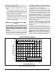
• The Refrigerant Charging Charts (Figures 6 - 10,
pages 13 - 15) are applicable to listed assemblies
of equipment and at listed airflows for the indoor coil.
Assemblies of indoor coils and outdoor units not listed
are not recommended. To properly charge these units:
1. Read all Installation Instructions first.
2.Complete any brazing operations. (e.g. Split system
line-sets)
3. Leak check and evacuate the whole system using proper
methods.
4. Purge the nitrogen holding charge.
5. Evacuate the unit to 350-500 microns.
6. Allow the unit to remain under vacuum for at least 30
min.
7. Weigh-In the proper amount of new (or reclaimed)
R-410A refrigerant. Refer to Table 2 or the units rating
label to determine the correct amount of charge.
• Refrigerant charging charts are applicable only to
matched assemblies and listed airflows for the indoor
coil. Refer to Figures 6 - 9 (pages 13 - 14) and Table
2 for correct system charge.
• Outdoor units with indoor coils not listed are not
recommended. Deviations from rated airflows or non-
listed combinations may require modification to the
expansion device and refrigerant charging procedures
for proper and efficient system operation.
• Therefrigerantchargecanbecheckedandadjusted
through the service ports provided external to the
outdoor unit. Use only gage line sets which have a
“Schrader” depression device present to actuate the
valve.
Charging the Unit in AC Mode with Outdoor
Temperatures Above 55° F
(for optimized sub-cooling of 10° F to 12° F)
1. With the system operating at steady-state, measure the
liquid refrigerant pressure (in psig) at the outdoor unit
service valve.
Anti Short Cycle Timer Test
The 3-minute time delay feature can be bypassed by
shorting the TEST pins together.
Heating Mode
When the TEST pins are shorted together for more than
1-second, the control will switch between defrost mode
and heating mode (as described in the Defrost Test
Procedure section).
Cooling Mode
When the TEST pins are shorted together for more than
1-second, the Anti Short Cycle Timer will be bypassed.
Optional Equipment
A functional checkout should be performed in accordance
with the checkout procedures supplied with the equipment.
Adjustment of Refrigerant Charge
WARNING:
This split system heat pump is shipped charged
with R410A refrigerant and ready for installation.
If repairs make it necessary for evacuation and
charging, it should only be attempted by qualified
trained personnel thoroughly familiar with this
equipment. Under no circumstances should
the owner attempt to install and/or service this
equipment. Failure to comply with this warning
could result in property damage, personal injury,
or death.
After refrigerant line connections are completed, it is
required that you leak check and evacuate the indoor
section and all line connections (using proper methods)
beforenalizingthefullsystemrefrigerantcharge.
• Toachieveratedcapacityandefciency,thecompressor
must be exposed to refrigerant for at least 24 hours
prior to running and then the compressor must be run
for a minimum of 12 hours.
• Cooling mode charging charts are applicable only
to matched assemblies of this equipment and listed
airflows for the indoor coil. Outdoor units with non-
AHRI lsited indoor coils are not recommended and
deviations from rated airflows or non-listed combinations
may require modification to the expansion device and
refrigerant charging procedures for proper and efficient
system operation. Refer to Tables 3-9 (pages 11 - 13)
and Figures 5-11 (pages 13-16) for correct system
charging.
• Therefrigerantchargecanbecheckedandadjusted
through the service ports provided external to the
outdoor unit. Use only gage line sets which have a
“Schrader” depression device present to actuate the
valve. A common suction port for heating mode charging
is included and located on the compressor access panel
above the outdoor unit service valves.
• HeatModeVericationTables(Tables10-16,pages
18 - 20) are provided for quick reference when the unit
is in heating mode and for the inspection of the liquid
line pressures and temperatures.