
User Guide


7
thermostat. NOTE: The blower should also stop unless
fan switch is set to the ON position.
System Heating (Optional)
1. If heating equipment (furnace, air handler) is provided
with the system, lower the thermostat setpoint
temperature to the lowest temperature setting and
change the thermostat’s system mode to HEAT.
2. Gradually increase the thermostat’s setpoint
temperature to the maximum setting.
3. Verify the optional heating equipment (furnace or
electricheat)andindoorblowerenergize.Feeltheair
being circulated by the indoor blower and verify that
it is warmer than ambient temperature. Listen for any
unusual noises. If unusual sounds occur, determine the
source of the noise and correct as necessary.
NOTE: Other sources for heating (electric furnace, fossil
fuel furnace, air handler with electric heat options, etc.)
that interface with the heat pump should be functionally
checked to verify system operation and compatibility
with the heat pump. Refer to the installation instructions
for this equipment and perform a functional checkout in
accordance with the manufacturer’s instructions.
Short Cycle Protection
1. With the system operating in COOLING mode, record
the setpoint temperature setting of the thermostat.
2. Gradually raise the setpoint temperature until the outdoor
unitandindoorblowerde-energize.
3. Immediately lower the setpoint temperature of the
thermostat to its original setting and verify that the indoor
blowerisenergizedandthattheoutdoorunitremains
de-energized.
4. After approximately 3 minutes, verify that the outdoor
unitenergizesandthetemperatureoftheairsupplied
to the facility is cooler than ambient temperature.
Defrost Cycle Control
The defrost cycle is controlled by an Adaptive Demand
Defrost algorithm that monitors coil temperature and
ambient temperature. Other features of the of the demand
defrost board include:
• 4 Field selectable defrost termination temperatures
(50° F - 80° F coil temperature).
• Fieldselectablecompressordelayfeature.
• Highpressureandlowpressureswitches.
• Sensingofsecondstagecompressordemand.
• Test/speedupcapability.
• Anti short cycle timer (3 minutes) for compressor
protection.
• On board diagnostics with ashing LED for quicker
troubleshooting. See Table 3.
Control is uncalibrated when power is applied. Calibration
occurs after a defrost cycle. The control initiates this
sacrificial defrost after 34 minutes of accumulated
compressor run time in heating with coil temperature
below 35° F. The defrost cycle terminates if coil sensor
reaches selected termination temperature or after 14
minutes defrost.
Defrost function is disabled if coil temperature is above
35° F. If Ambient sensor is detected as open or shorted,
demand defrost will not operate and control will revert
to time/temperature defrost operation. If the outdoor coil
sensor is detected as open or shorted, the control will not
perform demand or time/temperature defrost operation.
NOTE: When the defrost cycle initiates, there will be a
30 second compressor delay going into and out of the
defrost cycle. This delay may be removed by removing
P6 connector on the board.
This 2-stage unit will defrost in second stage regardless
of the stage called for by the thermostat.
NOTE: All units are shipped from the factory with the
default termination temperature set at 70° F.
Defrost Test Procedure
1. Terminals R - C must have 18-30VAC present between
them in order for defrost sequences to be initiated.
2 With heat mode thermostat demand (Y connected to
R), short and hold the TEST pins together. This will
energize reversing valve to initiate a forced defrost.
NOTE: This will bypass the ASCD and allow the high
stage compressor to come on immediately (if the
REMOVE FOR NO DELAY jumper at P6 is removed). If
the REMOVE FOR NO DELAY jumper at P6 is installed,
thecompressorwillenergizeimmediatelyfollowinga
30-second delay.
3. Remove the short on the TEST pins.
• If the Coil temperature is above the Terminate
Temperature selection setting, the defrost cycle will
beterminated(reversingvalvewillde-energized).
• If the coil temperature is below the Terminate
Temperature election setting, the defrost cycle will
continue for 14 minutes or until the coil temperature
rises above the Terminate Temperature selection
setting. NOTE: Short the TEST pins for 1 second
or more to force the control out of defrost and back
to heating mode (reversing valve de-energized).
Compressor will turn on immediately (if the REMOVE
FOR NO DELAY jumper is removed).
• IftheREMOVEFORNODELAYjumperisinstalled,
thecompressorwillenergizeimmediatelyfollowing
a 30-second delay.
NOTE:IftheY2thermostatinputisenergized(2-stage
system), the second stage will turn on.
If the above steps will not initiate a defrost, replace the
defrost board.
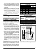
DIAGNOSTIC DESCRIPTION LED STATUS
Control Fault (No Power) Off
Normal Operation On
ASCD Delay Active
(with compressor demand)
1 Flash
Low Pressure Switch Lockout 2 Flashes
High Pressure Switch Lockout 3 Flashes
Ambient Sensor Fault 4 Flashes
Coil Sensor Fault 5 Flashes
Table 3. Control Diagnostic