
User Guide


5
the line-voltage leads to the terminals on the contactor
inside the control compartment.
• Useonlycopperwireforthelinevoltagepowersupply
to this unit as listed in Table 1. Use proper code agency
listed conduit and a conduit connector for connecting
the supply wires to the unit. Use of rain tight conduit is
recommended.
• 208/230Voltunitsareshippedfromthefactorywired
for 230 volt operation. For 208V operation, remove the
lead from the transformer terminal marked 240V and
connect it to the terminal marked 208V.
• Optionalequipmentrequiringconnectiontothepower
or control circuits must be wired in strict accordance
of the NEC (ANSI/NFPA 70), applicable local codes,
and the instructions provided with the equipment.
Grounding
WARNING:
The unit cabinet must have an uninterrupted or
unbroken electrical ground to minimize personal
injury if an electrical fault should occur. Do not
use gas piping as an electrical ground!
This unit must be electrically grounded in accordance
with local codes or, in the absence of local codes, with
the National Electrical Code (ANSI/NFPA 70) or the CSA
C22.1 Electrical Code. Use the grounding lug provided in
the control box for grounding the unit.
Thermostat/LowVoltageConnections
• Thermostatconnectionsshouldbemadeinaccordance
with the instructions supplied with the thermostat and
the indoor equipment. A typical installation with a heat
pump thermostat and air handler is shown in Figure 2.
• Theoutdoorunitisdesignedtooperatefroma24VAC
Class II control circuit. The control circuit wiring must
comply with the current provisions of the NEC (ANSI/
NFPA 70) and with applicable local codes having
jurisdiction.
• Thelowvoltagewiresmustbeproperlyconnectedto
the units low voltage terminal block. Recommended
wire gauge and wire lengths for typical thermostat
connections are listed in Table 2.
• The thermostat should be mounted about 5 feet
above the floor on an inside wall. DO NOT install the
thermostat on an outside wall or any other location
where its operation may be adversely affected by radiant
heat from fireplaces, sunlight, or lighting fixtures, and
convective heat from warm air registers or electrical
appliances. Refer to the thermostat manufacturer’s
instruction sheet for detailed mounting and installation
information.
Outdoor Fan Motor
Iftheunitutilizesa 2-speed condenserfanmotor,this
motor will operate on low speed when in low cooling,
and on high speed when in high cooling. A relay within
the control area switches the fan motor from low to high
speed using the call for high cooling as the trigger. Other
modelsthatutilizeBLDCxedtorquevariablespeedfan
motors will not require a relay.
Table 2. Thermostat Wire Gauge
Thermostat
Wire Gauge
Recommended T-Stat Wire
Unit to T-Stat (Length in FT)
2-Wire
(Heating)
5-Wire
(Heating/Cooling)
24 55 25
22 90 45
20 140 70
18 225 110
COPPER WIRE SIZE — AWG
(1%VoltageDrop)
Supply Wire Length-Feet
Supply Circuit
Ampacity
200 150 100 50
6 8 10 14 15
4 6 8 12 20
4 6 8 10 25
4 4 6 10 30
3 4 6 8 35
3 4 6 8 40
2 3 4 6 45
2 3 4 6 50
2 3 4 6 55
1 2 3 4 60
WireSizebasedonN.E.C.for60°typecopperconductors.
Table 1. Copper Wire Size
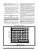
Figure 2. Typical 2 - Stage Heat Pump w/ Optional
OutdoorThermostatandVariableSpeedAirHandler
GRW2 CEOY1
Thermostat
OD
Stat
O
Y1
R
C
Air Handler
Heat Pump OD
Section
W
2
E
W2
W1
O
Y/Y2
G
R
C
Y2
Y2
W1
W3
Y1
NOTE: Jumper
W1 & W2 together
for shorter staging
time.