
User Guide


13
AMB
HPS
W2 OUT
LPS
Y
OUT
Y2
OUT
Y2
W2 IN
L
COIL
C
Y
O
R
DF1 DF2
RV
BLACK
RED
OUTDOOR
FAN MOTOR
T1 T2
L1 L2
COMPRESSOR
HPS
LPS
RV COIL
CCH
BLACK
RED
BLUE
ORANGE
H
F
C
R
S
TO THERMOSTAT
AMB SENSOR
OD SENSOR
CONTACTOR
DEFROST BOARD
LFT
RT
S
L
H
C
NC
NO
COM
GRND
GROUNDING
SCREW
FAN RELAY
CAPACITOR
L1 L2
YELLOW
C
TERMINAL
BLOCK
D
RED
HPS
W2 OUT
LPS
Y
OUT
Y2
OUT
Y2
W2
IN
COIL
C
Y
O
AMBDF1DF2
RV
DEFROST BOARD
S
L
H
R
H
F
C
RV COIL
LPS
HPS
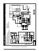
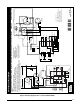
WIRING DIAGRAM
711016
1209
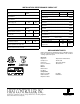
FIELD WIRING
LEGEND:
LOW VOLTAGE
HIGH VOLTAGE
YELLOW
BLACK
YELLOW
BLACK
BLACK
BLACK
BLACK
BLUE
YELLOW
R
S
C
OFR
CCH
L2
L1
T2
T1
OUTDOOR
FAN MOTOR
COMPRESSOR
CAPACITOR
CC
FRC
Y
O
C
Y2
CSC
AMB
SENSOR
COIL
SENSOR
208/230V
208/230V
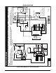
Two Stage Split System Heat Pump With Demand Defrost and Two Speed Fan Motor Single Phase / 60 Hz.
NOTES:
1. Disconnect all power before servicing.
2. For supply connections use copper conductors only.
3. Not suitable on systems that exceed 150 volts to ground.
4. For replacement wires use conductors suitable for 105
5. For ampacities and overcurrent protection, see unit rating plate.
6. Connect to 24 vac/40va/class 2 circuit. See furnace/airhandler installation
instructions for control circuit and optional relay/transformer kits.
1. Couper le courant avant
de faire letretien.
2. Employez uniquement des
conducteurs en cuivre.
3. Ne convient pas aux installations
de plus de 150 volt a la terre.
°C
YELLOW
ORANGE
BLACK
WHITE
BLUE
BROWN
W1
¢711016q¤
Figure 9. Wiring Diagram for 3 Ton Standard Models