
user manual


6
VI. STANDARD UNIT FEATURES — 6
1
⁄2 AND 7
1
⁄2
CABINET — Galvanized steel with a durable powder coat paint finish. The cabinet front
and sides are formed into a one piece unitized design with stamped louvers to provide
protection for the condenser coils.
SERVICE ACCESS — Control box with separation between line and control voltages,
as well as compressor and other refrigerant controls are accessible through removable
t
op and side panels (without affecting normal operation of unit).
Condenser fan motors are mounted on removable top panels which bring the motors out
to you and expose entire condenser coil for cleaning.
COMPRESSOR — Hermetically sealed with internal high temperature protection and
d
urable insulation on motor windings. The compressor is mounted on rubber grommets
to reduce vibration and noise.
CONDENSER COILS — Constructed with copper tubes and aluminum fins mechanical-
ly bonded to tubes for maximum heat transfer capabilities. All coil assemblies are leak
t
ested.
REFRIGERANT CONNECTIONS — All field sweat joints are made external of the unit
and are located close to the ground for a neat looking installation.
LOW AMBIENT CONTROL — A pressure sensitive fan cycling control allows operation
of units down to to 0°F.
HIGH PRESSURE CONTROL — Manual reset control deactivates system if abnormally
high pressure occurs.
LOW PRESSURE CONTROL — Automatic reset control deactivates system if abnor-
mally low pressure or refrigerant loss occurs.
SERVICE VALVES — Standard on liquid line and suction line. Allows outdoor section
to be isolated from indoor coil.
FILTER DRIER — Standard, field installed. Helps maintain system cleanliness.
CONDENSER FAN MOTORS — Direct-drive, PSC single-phase motors.
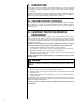
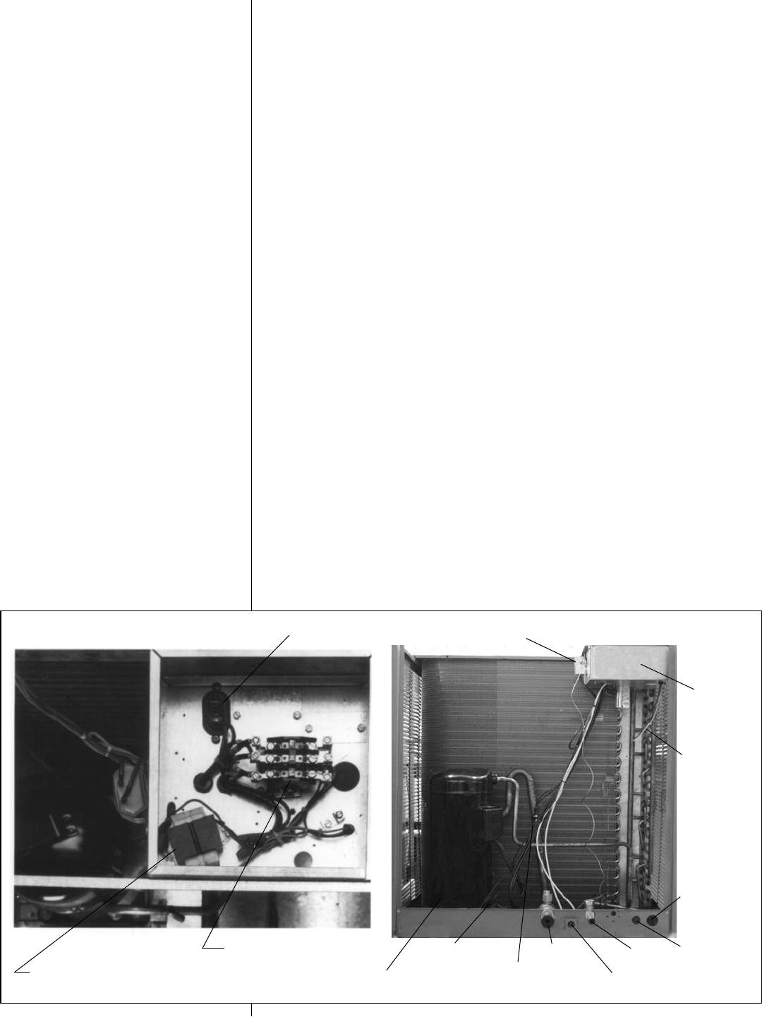
TRANSFORMER — Step down type, from Line to 24 volts. (Refer to Figure 2.)
CONTACTOR — (Refer to Figure 2.) The contactor is an electrical switch which oper-
ates the compressor and condenser fans. Its 24 volt coil is activated through the High
Pressure Control and Low Pressure Control on a call for cooling.
CAPACITORS — Help provide starting torque necessary to boost the condenser fan
motors to operating speed by directing their stored energy to the starter winding in step
with the running winding.
EQUIPMENT GROUND — Lug for field connection of ground wire.
TESTING — All units are run tested at the factory prior to shipment.
CONTROL TRANSFORMER
SCROLL
COMPRESSOR
LOW
PRESSURE
SWITCH
CRANKCASE
HEATER
SUCTION
VALVE
HIGH PRESSURE
SWITCH
LIQUID
VALVE
LOW VOLTAGE
ENTRY
HIGH VOLTAGE
ENTRY
LOW VOLTAGE
CONNECTION
LOW AMBIENT
CONTROL
CONTROL
BOX
COMPRESSOR CONTACTOR
FIGURE 2
6
1
⁄2 & 7
1
⁄2 TON FEATURES
CAPACITOR