
user manual


17
15. Note weight of refrigerant tank.
16. When system has stabilized, check superheat at the suction line service valve. The
actual line temperature should be 15° to 25°F higher than the saturation temperature
corresponding to the suction pressure. If superheat is measured at evaporator, the
actual line temperature should be 15° to 20° higher than the saturation temperature
corresponding to the suction pressure.
17. Close service ports on suction and liquid valves. Remove service gauges.
18. Replace service port caps and valve stem caps. These caps must be replaced to
prevent leaks.
19. Record total charge quantity on rating plate.
XVIII. SEQUENCE OF OPERATION — 6
1
⁄2
XVIII. AND 7
1
⁄2 TON
1. When the room temperature is higher than the thermostat setting, the thermostat con-
tacts close and energize the compressor contactor (CC) through the high pressure,
and low pressure controls. If the unit has “short cycled” and the optional anti-short
cycle timer (TDC) has been supplied, the contactor coil (CC) will remain de-energized
for up to five (5) minutes.
2. The system will continue cooling operation, as long as the contacts of all safety
devices are closed and until the thermostat is satisfied.
3. When the thermostat is satisfied, compressor or contactor (CC) is de-energized.
XIX. ACCESSORIES
A. ANTI-SHORT CYCLE TIMER
ANTI-SHORT-CYCLE TIMER — Prevents restarting of unit for five minutes if shut down
for any reason. (See wiring diagram and schematic in this manual for proper location
and installation; item TDC.)
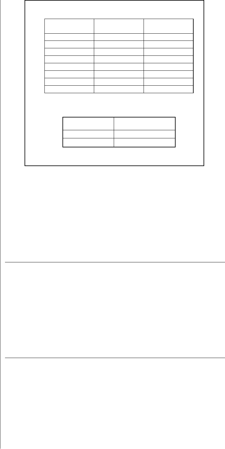
1/2 1.06 0.04
5/8 1.65 0.07
3/4 2.46 0.10
7/8 3.28 0.13
1 1/8 0.22
1 3/8 0.34
1 5/8 0.48
2 1/8 0.84
Vapor
oz/ft
Tube Size
O.D., In.
Liquid
oz/ft
BASIC SYSTEM CHARGE*
Unit
Model
RSG078 178 [5046]
RSG090 242 [6861]
Basic System
Charge, Oz. [g] *
*-System with 0 Feet [0] of tubing.
TABLE 6
R
EQUIRED OZS. R-410A PER FT. OF TUBING
Quantities based on 110°F liquid and 45°F vapor.