INSTALLATION, OPERATION & MAINTENANCE MANUAL Residential Packaged Geothermal Heat Pump HEV/H Series 2 to 5 Tons Heat Controller, LLC. • 1900 Wellworth Ave. • Jackson, MI 49203 • (517)787-2100 • www.heatcontroller.
Installation, Operation & Maintenance HEV/H SERIES Heat Controller, LLC. TABLE OF CONTENTS Model Nomenclature ............................................................................................3 Safety Instructions ................................................................................................4 Pre-Installation......................................................................................................5 Physical Data......................................................
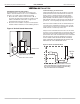
HEV/H SERIES Heat Controller, LLC.
Installation, Operation & Maintenance HEV/H SERIES Safety Warnings, cautions and notices appear throughout this manual. Read these items carefully before attempting any installation, service or troubleshooting of the equipment. Heat Controller, LLC. CAUTION: Indicates a potentially hazardous situation or an unsafe practice, which if not avoided could result in minor or moderate injury or product or property damage.
Heat Controller, LLC. HEV/H SERIES Installation, Operation & Maintenance GENERAL INFORMATION 6. Loosen compressor bolts on units equipped with Inspection compressor spring vibration isolation until the Upon receipt of the equipment, carefully check the shipment compressor rides freely on the springs. Remove against the bill of lading. Make sure all units have been shipping restraints. received. Inspect the packaging of each unit, and inspect REMOVE COMPRESSOR SUPPORT PLATE 1/4” each unit for damage.
HEV/H SERIES Installation, Operation & Maintenance Heat Controller, LLC. PHYSICAL DATA Model 024 030 Compressor (1 Each) Factory Charge HFC-410a, oz 036 042 048 060 Copeland UltraTech Two-Stage Scroll 51 48 54 70 80 84 1/2 [373] 1/2 [373] 1/2 [373] 3/4 [559] 3/4 [559] 1 [746] 9x7 [229 x 178] 9x7 [229 x 178] 9x8 [229 x 203] 9x8 [229 x 203] 10 x 10 [254 x 254] 11 x 10 [279 x 254] 1” 1” 1” 1” 1” 1” 1” 1” 1” 1” 1” 1” Air Coil Dimensions (H x W), in [mm] 20 x 17.
HEV/H SERIES Heat Controller, LLC. Installation, Operation & Maintenance HE - VERTICAL UPFLOW DIMENSIONAL DATA Overall Cabinet Vertical Upflow Model A Width B Depth C Height 024-030 in cm 22.4 56.9 22.4 56.9 40.5 102.9 036-042 in cm 22.4 56.9 26.0 66.0 46.5 118.1 048 -060 in cm 25.4 64.5 29.3 74.4 50.5 128.3 Water Connections - Standard Units Vertical Upflow Model 1 2 3 4 5 D Loop In E Loop Out Cond. HWG In HWG Out F G H Loop Water FPT HWG FPT 024 - 030 in cm 3.8 9.
HEV/H SERIES Installation, Operation & Maintenance Heat Controller, LLC. HE - VERTICAL UPFLOW DIMENSIONAL DATA Return Connection Standard Deluxe Filter Frame (+/- 0.10 in, +/- 2.5mm) Discharge Connection Duct Flange Installed (+/- 0.10 in, +/- 2.5mm) Vertical Upflow Model M Left Return N O Supply Width P Supply Depth Q Right Return R S Return Depth T Return Height U 024 - 030 in cm 7.4 18.8 4.2 10.7 13.9 35.3 14.0 35.6 6.7 17.0 2.2 5.6 18.0 45.7 18.0 45.7 1.0 2.
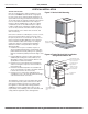
Heat Controller, LLC. HEV/H SERIES Installation, Operation & Maintenance VERTICAL INSTALLATION Vertical Unit Location Units are not designed for outdoor installation. Locate the unit in an INDOOR area that allows enough space for service personnel to perform typical maintenance or repairs without removing unit from the mechanical room/ closet. Vertical units are typically installed in a mechanical room or closet.
HEV/H SERIES Installation, Operation & Maintenance Heat Controller, LLC. VERTICAL INSTALLATION IN Condensate Piping for Vertical Units Install condensate trap at each unit with the top of the trap positioned below the unit condensate drain connection as shown in Figure 4. Design the depth of the trap (waterseal) based upon the amount of External Static Pressure (ESP) capability of the blower (where 2 inches [51mm] of ESP capability requires 2 inches [51mm] of trap depth).
Heat Controller, LLC. HEV/H SERIES Installation, Operation & Maintenance VERTICAL INSTALLATION Mounting Horizontal Units Horizontal units have hanger kits pre-installed from the factory as shown in Figure 5. Figures 7a and 7b shows a typical horizontal unit installation. Horizontal Unit Location Packaged units are not designed for outdoor installation.
HEV/H SERIES Installation, Operation & Maintenance Heat Controller, LLC.
HEV/H SERIES Heat Controller, LLC. Installation, Operation & Maintenance FIELD CONVERSION OF AIR DISCHARGE Field Conversion of Air Discharge Figure 8: Left Return Side to Back Overview - Horizontal units can be field converted between side (straight) and back (end) discharge using the instructions below. Remove Screws Water Connection End Return Air Note: It is not possible to field convert return air between left or right return models due to the necessity of refrigeration copper piping changes.
Installation, Operation & Maintenance HEV/H SERIES Heat Controller, LLC. WATER CONNECTION INSTALLATION External Flow Controller Mounting The Flow Controller can be mounted beside the unit as shown in Figure 12. Review the Flow Controller installation manual for more details. which holds the male pipe end against the rubber gasket, and seals the joint.
HEV/H SERIES Heat Controller, LLC. Installation, Operation & Maintenance GROUND-LOOP HEAT PUMP APPLICATIONS pressure is reached. Open the return valve and a pressure surge will be sent through the loop to help purge air pockets from the piping system. 4. Notice the drop in fluid level in the flush cart tank when the return valve is shut off. If air is adequately purged from the system, the level will drop only 1-2 inches (2.5 - 5 cm) in a 10” (25 cm) diameter PVC flush tank (about a half gallon [2.
HEV/H SERIES Installation, Operation & Maintenance Heat Controller, LLC. GROUND-LOOP HEAT PUMP APPLICATIONS Figure 12: Typical Ground-Loop Application Flow Controller Unit Power Disconnect Insulated Hose Kit Thermostat Wiring P/T Plugs Air Pad or Extruded polystyrene insulation board GROUND-WATER HEAT PUMP APPLICATIONS only be serviced by a qualified technician, as acid and special pumping equipment is required. Desuperheater coils can likewise become scaled and possibly plugged.
HEV/H SERIES Heat Controller, LLC. Installation, Operation & Maintenance GROUND-WATER HEAT PUMP APPLICATIONS Flow Regulation Flow regulation can be accomplished by two methods. One method of flow regulation involves simply adjusting the ball valve or water control valve on the discharge line. Measure the pressure drop through the unit heat exchanger, and determine flow rate from Table Tables10C. 8. Since Since the pressure is constantly varying, two pressure gauges may be needed.
HEV/H SERIES Installation, Operation & Maintenance Heat Controller, LLC. WATER QUALITY STANDARDS Table 3: Water Quality Standards Water Quality Parameter HX Material Closed Recirculating Open Loop and Recirculating Well Scaling Potential - Primary Measurement Above the given limits, scaling is likely to occur. Scaling indexes should be calculated using the limits below pH/Calcium Hardness Method All - pH < 7.
HEV/H SERIES Heat Controller, LLC. Installation, Operation & Maintenance HOT WATER GENERATOR The HWG (Hot Water Generator) or desuperheater option provides considerable operating cost savings by utilizing heat energy from the compressor discharge line to help satisfy domestic hot water requirements. The HWG is active throughout the year, providing virtually free hot water when the heat pump operates in the cooling mode or hot water at the COP of the heat pump during operation in the heating mode.
HEV/H SERIES Installation, Operation & Maintenance Heat Controller, LLC. HOT WATER GENERATOR ANTI-SCALD VALVE PIPING CONNECTIONS Installation The HWG is controlled by two sensors and the DXM2 microprocessor control. One sensor is located on the compressor discharge line to sense the discharge refrigerant temperature. The other sensor is located on the HWG heat exchanger’s “Water In” line to sense the potable water temperature.
HEV/H SERIES Heat Controller, LLC. Installation, Operation & Maintenance HOT WATER GENERATOR ensure that there is no air remaining in the tank. 4. Inspect all work for leaks. 5. Before restoring power or fuel supply to the water heater, adjust the temperature setting on the tank thermostat(s) to insure maximum utilization of the heat available from the refrigeration system and conserve the most energy.
HEV/H SERIES Installation, Operation & Maintenance Heat Controller, LLC. ELECTRICAL - LINE VOLTAGE ѥ WARNING! ѥ WARNING! To avoid possible injury or death due to electrical shock, open the power supply disconnect switch and secure it in an open position during installation. ѥ CAUTION! ѥ CAUTION! Use only copper conductors for field installed electrical wiring. Unit terminals are not designed to accept other types of conductors.
HEV/H SERIES Heat Controller, LLC. Installation, Operation & Maintenance ELECTRICAL - POWER WIRING Power Connection Line voltage connection is made by connecting the incoming line voltage wires to the “L” side of the contactor as shown in Figures 18. Consult Table 4 for correct fuse size. 208 Volt Operation All residential 208-230 Volt units are factory wired for 230 Volt operation.
HEV/H SERIES Installation, Operation & Maintenance Heat Controller, LLC. ELECTRICAL - LOW LO VOLTAGE WIRING Low Water Temperature Cutout Selection The DXM2 control allows the field selection of low water (or water-antifreeze solution) temperature limit by clipping jumper JW3, which changes the sensing temperature associated with thermistor LT1. Note that the LT1 thermistor is located on the refrigerant line between the coaxial heat exchanger and expansion device (TXV).
HEV/H SERIES Heat Controller, LLC. Installation, Operation & Maintenance ELECTRICAL - LOW VOLTAGE WIRING Accessory Connections A terminal paralleling the compressor contactor coil has been provided on the DXM2 CXM control. Terminal “A” is designed to control accessory devices, such as water valves. Note: This terminal should be used only with 24 Volt signals and not line voltage. Terminal “A” is energized with the compressor contactor. See Figure 23 or the specific unit wiring diagram for details.
Installation, Operation & Maintenance HEV/H SERIES Heat Controller, LLC. ELECTRICAL - THERMOSTAT WIRING Thermostat Installation The thermostat should be located on an interior wall in a larger room, away from supply duct drafts. DO NOT locate the thermostat in areas subject to sunlight, drafts or on external walls. The wire access hole behind the thermostat may in certain cases need to be sealed to prevent erroneous temperature measurement.
Heat Controller, LLC. HEV/H SERIES ECM BLOWER CONTROL The ECM fan is controlled directly by the DXM2 control board that converts thermostat inputs and CFM settings to signals used by the ECM motor controller. To take full advantage of the ECM motor features, a communicating thermostat should be used. The DXM2 control maintains a selectable operating airflow [CFM] for each heat pump operating mode. For each operating mode there are maximum and minimum airflow limits.
HEV/H SERIES Installation, Operation & Maintenance Heat Controller, LLC. BLOWER PERFORMANCE DATA Table 6: ECM Blower Performance Data Table Airflow in CFM with wet coil and clean air filter Model Max ESP (in. wg) Fan Motor (hp) Cooling Mode Range Default 024 030 036 042 048 060 0.75 0.5 0.6 0.6 0.75 0.
HEV/H SERIES Heat Controller, LLC.
HEV/H SERIES Installation, Operation & Maintenance Heat Controller, LLC. DXM2 CONTROLS DXM2 Control DXM2 is the next generation in controls is capable of 2-way communication between itself and smart components, like the communicating thermostat, fan motor and configuration/ diagnostic tool. DXM2 Control Start-up Operation The control will not operate until all inputs and safety controls are checked for normal conditions. The compressor will have a 5 minute anti-short cycle delay at power-up.
HEV/H SERIES Heat Controller, LLC. Installation, Operation & Maintenance DXM2 LAYOUT AND CONNECTIONS Service tool Communicating connection stat connection C P1 Gnd B- A+ 24V N.C. N.O. N.O.
HEV/H SERIES Installation, Operation & Maintenance Heat Controller, LLC. UNIT COMMISSIONING AND OPERATING CONDITIONS Operating Limits Environment – Units are designed for indoor installation only. Never install units in areas subject to freezing or where humidity levels could cause cabinet condensation (such as unconditioned spaces subject to 100% outside air). Power Supply – Voltage utilization shall comply with AHRI standard 110, voltage range A.
HEV/H SERIES Heat Controller, LLC. Installation, Operation & Maintenance UNIT STARTING AND OPERATING CONDITIONS Starting/Commissioning Conditions Table 9b: Commissioning Limits Commissioning Limits Air Limits Min. ambient air, DB Rated ambient air, DB Max. ambient air, DB Min. entering air, DB/WB Rated entering air, DB/WB Max. entering air, DB/WB Water Limits Min. entering water Normal entering water Max. entering water Normal Water Flow HE Series Cooling Heating 45°F [7°C] 80.
Installation, Operation & Maintenance HEV/H SERIES Heat Controller, LLC. UNIT START-UP AND OPERATING CONDITIONS operate in the proper sequence. Low water temperature cutout: Verify that low water temperature cut-out controls are set properly (LT1 - JW3). Miscellaneous: Note any questionable aspects of the installation. Unit and System Checkout BEFORE POWERING SYSTEM, please check the following: UNIT CHECKOUT Shutoff valves: Insure that all isolation valves are open.
Heat Controller, LLC. HEV/H SERIES Installation, Operation & Maintenance UNIT START-UP PROCEDURE and comparing to Table 10. d. Check the elevation and cleanliness of the condensate lines. Dripping may be a sign of a blocked line. Check that the condensate trap is filled to provide a water seal. e. Refer to Table 9. Check the temperature of both entering and leaving water. If temperature is within range, proceed with the test.
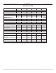
HEV/H SERIES Installation, Operation & Maintenance Heat Controller, LLC. UNIT OPERATING CONDITIONS Table 11: Water Temperature Change Through Heat Exchanger Table 10: HE Coax Water Pressure Drop Model GPM Pressure Drop (psi) 30°F 50°F 70°F 90°F 024 Rev B 2.5 3.0 3.8 4.5 6.0 0.8 1.2 1.8 2.7 3.9 0.3 0.6 1.1 1.6 2.8 0.2 0.5 0.9 1.2 2.2 0.2 0.5 0.8 1.2 2.0 030 3.0 3.8 4.5 6.0 7.5 1.7 2.3 2.7 3.8 5.1 0.9 1.2 1.6 2.4 3.5 0.8 1.1 1.4 2.2 3.1 0.8 1.1 1.4 2.1 2.9 036 Rev B 4.0 6.0 6.8 8.0 9.
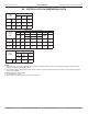
HEV/H SERIES Heat Controller, LLC. Installation, Operation & Maintenance UNIT OPERATING CONDITIONS Table 13: HE Series Typical Unit Operating Pressures and Temperatures 024 Entering Water Temp °F Full Load Cooling - without HWG active Water Flow GPM/ton 1.5 2.25 3 1.5 2.25 3 1.5 2.25 3 1.5 2.25 3 1.5 2.
HEV/H SERIES Installation, Operation & Maintenance Heat Controller, LLC. UNIT OPERATING CONDITIONS Table 13: HE Series Typical Unit Operating Pressures and Temperatures: Continued 042 Full Load Cooling - without HWG active Entering Water Temp °F Water Flow GPM/ton Suction Pressure PSIG Discharge Pressure PSIG 30* 1.5 2.25 3 50 1.5 2.25 3 121-131 120-130 120-130 230-250 200-240 164-184 10-15 11-16 11-16 10-15 8-13 6-11 20.5-22.5 15.2-17.2 9.8-11.8 70 1.5 2.
Heat Controller, LLC. HEV/H SERIES Installation, Operation & Maintenance PREVENTIVE MAINTENANCE Water Coil Maintenance (Direct ground water applications only) If the system is installed in an area with a known high mineral content (125 P.P.M. or greater) in the water, it is best to establish a periodic maintenance schedule with the owner so the coil can be checked regularly. Consult the well water applications section of this manual for a more detailed water coil material selection.
Installation, Operation & Maintenance HEV/H SERIES Heat Controller, LLC. TROUBLESHOOTING General If operational difficulties are encountered, perform the preliminary checks below before referring to the troubleshooting charts. • Verify that the unit is receiving electrical supply power. • Make sure the fuses in the fused disconnect switches are intact.
HEV/H SERIES Heat Controller, LLC. Installation, Operation & Maintenance DXM2 PROCESS FLOW CHART WARNING! WARNING! HAZARDOUS VOLTAGE! DISCONNECT ALL ELECTRIC POWER INCLUDING REMOTE DISCONNECTS BEFORE SERVICING. Failure to disconnect power before servicing can cause severe personal injury or death.
HEV/H SERIES Installation, Operation & Maintenance Heat Controller, LLC.
HEV/H SERIES Heat Controller, LLC. Installation, Operation & Maintenance FUNCTIONAL TROUBLESHOOTING (CONT.) Fault IFC Fault Code 13 Internal Flow Controller Fault Htg Clg Possible Cause X X Solution No pump output signal Check DC voltage between A02 and GND - should be between 0.5 and 10 VDC with pump active Low pump voltage Check line voltage to the pump No pump feedback signal Check DC voltage between T1 and GND.
HEV/H SERIES Installation, Operation & Maintenance Heat Controller, LLC. TROUBLESHOOTING FORM HEATING CYCLE ANALYSIS - PSI SAT °F °F Refrigerant Type AIR COIL SUCTION °F COMPRESSOR : EXPANSION VALVE R-410A R22 COAX DISCHARGE HWG °F °F °F FP2: HEATING LIQUID LINE FLASH GAS LINE °F FP1 SENSOR PSI °F PSI WATER IN SAT °F PSI WATER OUT Look up pressure drop in I.O.M. or spec. catalog to determine flow rate.
Heat Controller, LLC.
Revision History Date Page # Description 6 June, 13 26, 27 Thermostat Verbiage Corrected 22 April, 13 All 024, 036 Rev B Info Added Design, material, performance data and components subject to change without notice.