DMC24DB-1, DMH24DB-1 DMC36TB-1, DMH36TB-1
Room Air Conditioner Installation Manual TABLE OF CONTENTS Installation Requirements Required Tools Installation Parts Provided .........................................3 Safety Precautions ......................................................4 Installation of Indoor, Outdoor Unit...........................9 Select the best location ...........................................9 Piping length and elevation ....................................10 Fixing Installation Plate ...................................
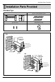
Installation Parts Provided Installation Parts Provided Standard Type Installation plate Type "A" screws and plastic anchors Holder Remote Control Type "B" screws 24k Air Intake (side, rear) more than 20cm (7.9 inch) more than 20cm (7.9 inch) Control cover Connecting wire Connection pipe Drain hose more than 70cm (27.6 inch) Air Outlet 36k Air Intake (side, rear) more than 30cm (11.8 inch) more than 30cm (11.8 inch) Control cover Connecting wire Connection pipe Drain hose more than 70cm (27.
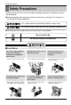
Safety Precautions Safety Precautions To prevent the injury of the user or other people and property damage, the following instructions must be followed. ■ Incorrect operation due to ignoring instruction will cause harm or damage. The seriousness is classified by the following indications. This symbol indicates the possibility of death or serious injury. This symbol indicates the possibility of injury or damage to properties only. ■ The meanings of the symbols used in this manual are as shown below.
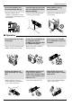
Safety Precautions Be sure the installation area does not deteriorate with age. Install the indoor unit on the wall where the height from the floors more than 8ft(2.4m) Do not handle the pipe by yourself(customer) • If the base collapses, the air conditioner could fall with it, causing property damage, product failure, and personal injury. • There are sharp moving parts that could cause personal injury. • High-Pressure refrigent may cause personal injury. 8ft(2.
Safety Precautions Stop operation and close any window in storm or hurricane. before the hurricane arrives. Do not open the inlet grill of the product during operation. (Do not touch the electrostatic filter, if the unit is so equipped.) When the product is soaked (flooded or submerged), contact an Authorized Service Center. • There is risk of property damage, failure of product, or electric shock. • There is risk of physical injury, electric shock, or product. • There is risk of electrical shock.
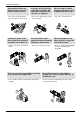
■ Installation Always check for gas(refrigerant) leakage after installation or repair of product. Install the drain hose to ensure that water is drained away properly. Keep level even when installing the product. • Low refrigerant levels may cause product failure. • A bad connection may cause water leakage. • To avoid vibration or water leakage. 90° Do not install the product where the noise or hot air from the outdoor unit could offend the neighbors.
Safety Precautions Use a soft cloth to clean. Do not use harsh detergents, solvents, etc. Do not touch the metal parts of the product when removing the air filter. They are very sharp! Do not step on or put anything on the product. (outdoor unit) • There is risk of fire, electric shock or damage to the plastic parts of the product. • There is risk of personal injury. • There is risk of personal injury and failure of product. Always insert the filter securely.
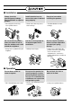
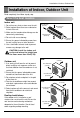
Installation of Indoor, Outdoor Unit Installation of Indoor, Outdoor Unit Read completely, then follow step by step. Select the best location Indoor unit 1. Do not have any heat or steam near the unit. More than 5cm (2.0 inch) 2. Select a place where there are no obstacles in front of the unit. 3. Make sure that condensation drainage can be conveniently routed away. More than 5cm (2.0 inch) More than 2.3m (90.6 inch) 4. Do not install near a doorway. More than 5cm (2.0 inch) 5.
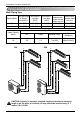
Installation of Indoor, Outdoor Unit Piping length and elevation Multi Piping Type Max total length Capacity(Btu/h) of all pipes (A+B/A+B+C) Max length of each pipe (A/B/C) Min length of each pipe (A/B/C) 24k 30m(100ft) 15m(50ft) 3m(10ft) 36k 45m(150ft) 15m(50ft) 3m(10ft) Max Elevation Max elevation between each between indoor indoor unit and units (h2) outdoor unit (h1) 7.5m(25ft) 7.5m(25ft) 7.5m(25ft) 7.
Installation of Indoor, Outdoor Unit Fixing Installation Plate The wall you select should be strong and solid enough to prevent vibration 1. Mount the installation plate on the wall with type "A" screws. If mounting the unit on a concrete wall, use anchor bolts. • Mount the installation plate horizontally by aligning the centerline using a level. Installation Plate Chassis Hook Type "A" screw 2. Measure the wall and mark the centerline.
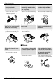
Flaring Work and Connection of Piping Flaring Work and Connection of Piping Flaring work Main cause for gas leakage is due to defect in flaring work. Carry out correct flaring work in the following procedure. Cut the pipes and the cable. 1. Use the piping kit accessory or the pipes purchased locally. 2. Measure the distance between the indoor and the outdoor unit. Copper pipe Slanted Uneven Rough 90° 3. Cut the pipes a little longer than measured distance. 4. Cut the cable 1.5m (5.
Flaring Work and Connection of Piping Check 1. Compare the flared work with the figure by. Smooth all round Inside is shiny without scratches 2. If a flared section is defective, cut it off and do flaring work again. = Improper flaring = Even length all round Inclined Surface Cracked Uneven damaged thickness Connecting the Piping Indoor 1. Prepare the indoor unit's piping and drain hose for installation through the wall. 2.
Flaring Work and Connection of Piping 4. Indoor unit installation Hook the indoor unit onto the upper portion of the installation plate.(Engage the two hooks of the rear top of the indoor unit with the upper edge of the installation plate.) Ensure that the hooks are properly seated on the installation plate by moving it left and right. Connecting cable Drain hose Press the lower left and right sides of the unit against the installation plate until the hooks engage into their slots(clicking sound).
Flaring Work and Connection of Piping For left rear piping 1. Route the indoor tubing and the drain hose to the required piping hole position. 1 2 Connecting cable 2. Insert the piping, drain hose, and the connecting cable into the piping hole. 3. Insert the connecting cable into the indoor unit. • Don't connect the cable to the indoor unit. • Make a small loop with the cable for easy connection later. Drain pipe 4. Tape the drain hose and the connecting cables. 5.
Flaring Work and Connection of Piping Wrap the insulation material around the connecting portion. 1. Overlap the connection pipe heat insulation and the indoor unit pipe heat insulation material. Bind them together with vinyl tape so that there may be no gap. 2. Wrap the area which accommodates the rear piping housing section with vinyl tape. Plastic bands Insulation material Indoor unit piping Connection pipe Vinyl tape (wide) Wrap with vinyl tape Pipe Vinyl tape(narrow) Connecting cable 3.
Flaring Work and Connection of Piping Installation Information. For left piping. Follow the instruction below. Good case • Press on the upper side of clamp and unfold the tubing to downward slowly. Bad case • Following bending type from right to left may cause damage to the tubing.
Flaring Work and Connection of Piping Outdoor Align the center of the pipings and sufficiently tighten the flare nut by hand. Finally, tighten the flare nut with torque wrench until the wrench clicks. • When tightening the flare nut with torque wrench, ensure the direction for tightening follows the arrow on the wrench. Outside diameter mm inch Ø6.35 1/4 Ø9.52 3/8 Outdoor unit 24k A-UNIT Gas side piping Torque kg.m(lbf.ft) B-UNIT Liquid side piping 1.8(13.0) 4.2(30.
Connecting the Cable between Indoor Unit and Outdoor Unit Connecting the Cable between Indoor Unit and Outdoor Unit Connect the cable to the Indoor unit. Connect the cable to the indoor unit by connecting the wires to the terminals on the control board individually according to the outdoor unit connection. (Ensure that the color of the wires of the outdoor unit and the terminal No. are the same as those of the indoor unit.) The earth wire should be longer than the common wires.
Connecting the Cable between Indoor Unit and Outdoor Unit Connect the cable to the Outdoor unit. 1. Remove the cover control from the unit by loosening the screw. Connect the wires to the terminals on the control board individually as the following. Outdoor unit Terminal block Over 5mm 2. Secure the cable into the control board with the strain relief clamp. Holder for power supply cord 3. Refix the cover control to the original position with the screw.
Connecting the Cable between Indoor Unit and Outdoor Unit Connection method of the connecting cable(Example) (1) Remove two-caps on the conduit panel. (2) Make a hole appropriate for the passage of connection cable through on cap by tool. (for low voltage line) (3) Pass the connecting cable through the hole. (4) Properly connect the cable on the terminal block.
Connecting the Cable between Indoor Unit and Outdoor Unit CAUTION! Provide a circuit breaker between the power source and the outdoor unit as shown below. Size breaker per the Maximum Fuse or Circuit Breaker (MOC) rating on the unit rating plate. Main power source Air Conditioner Circuit Breaker Use a circuit breaker or time delay fuse. Model Power source 24k 36k 1ø,230/208V 1ø,230/208V Connect the cable to the indoor unit 1.
Checking the Drainage, Forming the Pipings and Long Pipe Setting Checking the Drainage, Forming the Pipings and Long Pipe Setting Checking the drainage To check the drainage. 1. Pour a glass of water on the evaporator. 2. Ensure the water flows through the drain hose of the indoor unit without any leakage and goes out the drain exit. Drain piping 1. The drain hose should point downward for easy drain flow. Downward slope 2. Examples of incorrect drain piping.
Checking the Drainage, Forming the Pipings and Long Pipe Setting Forming the piping Form the piping by wrapping the connecting portion of the indoor unit with insulation material and secure it with two kinds of vinyl tape. • If you want to connect an additional drain hose, the end of the drain outlet should be routed above the ground. Secure the drain hose appropriately. Seal a small opening around the pipings with gum type sealer.
Air Purging and Evacuation Air Purging and Evacuation Air and moisture remaining in the refrigerant system have undesirable effects as indicated below. 1. Pressure in the system rises. 2. Operating current rises. 3. Cooling(or heating) efficiency drops. 4. Moisture in the refrigerant circuit may freeze and block capillary tubing. 5. Water may lead to corrosion of parts in the refrigeration system.
Air Purging and Evacuation Evacuation 1. Connect the charge hose end described in the preceding steps to the vacuum pump to evacuate the tubing and indoor unit. Confirm the "Lo" knob of the manifold valve is open. Then, run the vacuum pump. The operation time for evacuation varies with tubing length and capacity of the pump. The following table shows the time required for evacuation.
Charging Charging ■ Each outdoor unit is factory charged (nameplate charge) for the evaporator as well as a 7.5m(25ft) line set for each indoor line. Any time total line set is used either shorter or longer then the nominal 22.5m(75ft: for tri-zone) line set length the refrigerant charge has to be adjusted. ■ Whether the line set is made shorter or longer you must adjust the charge based on how many ft of tubing are either added or removed based on 20g(0.22oz) of R-410A per meter(foot).
Test Running Test Running 1. Check that all tubing and wiring have been properly connected. 2. Check that the gas and liquid side service valves are fully open. Prepare remote control Remove the battery cover by pulling it according to the arrow direction. Insert new batteries making sure that the (+) and (–) of battery are installed correctly. Reattach the cover by pushing it back into position. Bolt : • Use 2 AAA(1.5volt) batteries. Do not use rechargeable batteries.
Specifications and performance data subject to change without notice. HEAT CONTROLLER, INC. 1900 WELLWORTH AVENUE • JACKSON, MICHIGAN 49203 THE QUALITY LEADER IN CONDITIONING AIR P/No.