
Quick Start Manual


TOXIC CHEMICALS SUCH AS USED FOR FREEZE
PROTECTION, BOILER TREATMENT OR
NONPOTALE WATER HEATING APPLIANNCES
MUST NEVER BE INTRODUCED INTO A POTABLE
WATER/SPACE HEATING SYSTEM.
IF THE SYSTEM REQUIRES WATER AT
TEMPERATURES HIGHER THAN REQUIRED FOR
OTHER USES, A TEMPERING MEANS, SUCH AS A
MIXING VALVE, MUST BE INSTALLED TO
TEMPER THE WATER FOR THOSE OTHER USES
IN ORDER TO REDUCE SCALD HAZARD
POTENT
IAL. MIXING VALVES ARE AVAILABLE
AT PLUMB
ING SUPPLY OR HARDWARE STORES.
FOLLOW MANUFACTURER’S INSTURCTIONS
FOR INSTALLATION OF THESE VALVES.
After piping has been installed, fill the system with water
and check connections for leaks. To ensure complete
filling of the system follow start-up procedure section.
E. POWER WIRING
Refer to the unit’s nameplate for specific electrical data.
DISCONNECT POWER AT MAIN FUSE OR
CIRCUIT BREAKER DISTRIBUTION PANEL
BEFORE WIRING UNIT TO PREVENT SHOCK OR
FIRE HAZARD.
Use copper conductors only
.
Tighten all wire connectors
. Refer to unit nameplate for
minimum circuit ampacity. For correct wire size, refer to
the National Electrical Code. Use 75C minimum wire in
unit wiring compartment.
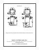
NOTE:
SEE UNIT FOR COMPLETE WIRING DIAGRAM
LOCATED ON BLOWER HOUSING.
F. CONTROL WIRING
Field connections are made to the low voltage terminal
strip. Consult installation instructions provided with
accessory items for specific information on control
wiring. Use 18 AWG control conductors are
recommended for lengths up to 100 feet. Class 2 wiring
is acceptable. Do not short control leads. Transformer
burn-out will result. Set thermostat heat anticipator at
0.15 amps for air handler.
G. BLOWER MOTOR
Units are equipped with a three-speed blower motor.
Two factory-selected motor speed leads are connected to
the fan relay (FR) to provide automatic speed change for
heating and cooling airflow volumes. The pre-selected motor
speeds would normally not have to be changed in the field.
All AHG models contain a blower “ON” time delay (BDR) as
well as a post purge timer (TDR) that delays the blower
tu
rning off at the end of the cooling cycle, this improves
en
ergy efficiency. Terminal number 4 on the fan relay (FR) is
the cooling blower speed and terminal number 6 on the fan
relay (FR) is the heating blower speed.
H. REFRIGERANT PIPING
All air handlers have DX refrigerant cooling coils installed;
liquid and suction piping should be sized in accordance with
condensing unit manufacturer’s recommendations. An
adapter may be required to make the transition between the
line set and the coil connector. The evaporator coil has sweat
copper connections. The suction line is a swaged solder cup
connection. The liquid line connection is m
ade to a tail piece
portion of the TXV. Remove the nut on the inlet to the
ex
pansion valve and place it on the tail piece prior to brazing
the liquid line. DO NOT connect the tail piece to the TXV
until the liquid line has been brazed to the tail piece.
Refrigerant lines should be soldered with silver solder or
another high temperature brazing alloy. Dry nitrogen must
flow through the refrigerant
lines during the brazing operation
to prevent oxidation.
I. REFRIGERANT FLOW CONTROL
As shipped, the TXV installed on the A-coil is for the
nominal capacity of a 13 SEER matched with Heat
Controller, Inc., condensing units. The TXV is for use on an
R-22 system. For other refrigerants, contact the factory. TXV
has a built-in check valve for reverse flow and is suitable for
heat pump operation. All are externally equalized with non-
adjustable superheat and have 15% bleed. Hard star
t
capability for outdoor units is not normally required when a
15
% bleed valve is used. The external equalizer line attached
to the TXV has a female flare nut and is attached to the
suction line at the coil. Install the attached to the suction line
at the coil. Install the TXV bulb to the suction line using the
bulb clamp furnished with the kit. The bulb should be
installed on a horizontal run of
the suction line of possible.
On a line less than 7/8” OD or over, the bulb should be
ins
talled in a position of about 4 or 8 o’clock. If the bulb
installation is made on a vertical run, the bulb should be
located at least 6 inches from any bend and on the tubing side
opposite the plane of the bend. On vertical bulb installations,
the bulbs should be positioned with the bulb capillary tube at
the
top. The bulb must be insulated using thermal
insulation to protect it from the effects of the surrounding
ambient temperature.
3