
Quick Start Manual

ARRANGEMENT
Unit is shipped from the factory arranged to be installed
in a vertical upflow or horizontal right to left airflow
position (standard) or field convertible to a horizontal left
to right airflow position.
Upflow Application
In an upflow application the discharge outlet is at the top.
Care should be taken to ensure unit is level to permit
proper condensate drainage. Normal upflow instal
lation
will be in a basement or closet. If installed in a closet, the
clos
et should have a platform framed in, with an opening
on top of the platform centered in the closet. Connect the
supply air outlet to a warm air plenum. Install return air
grilles from outside the closet to space below the
platform. Platform must be at least 10” above the floor.
Run all supply and return ductwork in accordanc
e with
local codes.
A “P” TRAP MUST BE INSTALLED IN THE COIL
DRAI
N LINE! CAP ALL UNUSED DRAIN FITTINGS.
Horizontal Application
Horizontal application will normally be used in an attic
or crawl space. This type of installation requires a return air
duct be attached to the air handler inlet. The opposite end
of the return air duct is attached to a return air filter grille
through the ceiling or wall
. Remove filter from unit if
filter grill is used. The unit is shipped in right to left
configuration.
TO ENSURE UNIT WILL NOT INTERFERE WITH
DRAI
NS AND REFRIGERANT LINES
MODIFICATION MUST BE MADE PRIOR TO
INSTALLING THESE LINES.
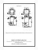
:snoitacilppa thgir ot tfel roF
1. Remove and set aside front panels.
2. Remove the coil support bracket (4-screws).
3. Remove horizontal drain pan retraining clip (1-
screw)
.
4. Carefully remove coil assembly and bottom
drain pan.
5. Move horizontal drain pan from left hand side of
coil to right side.
6. Install modified coil assembly back into unit.
7. R
einstall coil support bracket and horizontal
drain pan retraining clip
8. Determine drain holes being used and reposition
knockout caps.
9. Reinstall doors.
IT IS MANDATORY TO USE AN EMERGENCY
AUXILIARY DRAIN PAN WITH ANY COIL OR AIR
HANDLER INSTALLED IN AN ATTIC OR ABOVE
A FINISHED CEILING!
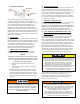
A. PIPING
Do not exceed 70 feet of piping between the air handler and
water heater. The water heater must be installed in
accordance with its installation instructions and local codes
and should be as close to the unit as practical, with the piping
system for the air handler as short as possible. The air
handler and water heater must be located indoors and
not subject to freezing temperature. If wate
r lines pass
through an unconditioned space, they must be protected so as
to p
revent freezing. See section on Low Temperature
Protection for Operational Coil Protection.
AIR HANDLER MUST BE LOCATED SO THAT IF ANY
CONNECTIONS SHOULD LEAK, WATER WILL NOT
CAUSE DAMAGE TO THE ADJACENT AREA. IF
DAMAGE MAY BE POSSIBLE, A SUITABLE DRAIN
PAN MUST BE INSTALLED UNDER THE AIR
HANDLER, NOT OVER 1 1/2 INCHES
DEEP, WITH
MINIMUM LENGTH AND WIDTH AT LEAST TWO
INCHES GREATER THAN THE AIR HANDLER
DIMENSIONS AND CONNECTED TO AN ADEQUATE
DRAI
N. THE MANUFACTURER ASSUMES NO
RESPONSIBILITY FOR ANY WATER DAMAGE IN
.RELDNAH RIA SIHT HTIW NOITCENNOC
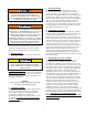
Total piping footage should not exceed 140 feet. All piping
should be ¾” copper or approved plastic. It is recommended
that a water shut off valve for the water heater
be located
close to the water heater. Isolation valves are additionally
recommended. See diagram above. Isolation and shutoff valves
are not included with air handler.
It is
recommended that any installed devices, which could
create a closed system, have a bypass and/or the system have
an expansion tank to relieve the pressure built by thermal
expansion in the water system. Contact the local water
supplie
r and/or plumbing contractor for assistance.
This air handler is designed to be used with a potable water
system.
H C
TUO NI
COLD TO W.H.
HOT TO
HOUSE
WATER HEATER
H02 AIR HANDLER
Typical water heater application.
(Circulating pump to air handler not shown.)
2