Installer’s Guide Installation and Operation Model: Soho-CE 0063-06 WARNING: If the information in these instructions is not followed exactly, a fire or explosion may result causing property damage, personal injury, or death. • Do not store or use gasoline or other flammable vapors and liquids in the vicinity of this or any other appliance. • What to do if you smell gas - Do not try to light any appliance - Do not touch any electrical switch. Do not use any phone in your building.
Read this manual before installing or operating this appliance. Please retain this owner’s manual for future reference. Congratulations Congratulations on selecting a Heat & Glo gas appliance The Heat & Glo gas appliance you have selected is designed to provide the utmost in safety, reliability, and efficiency. As the owner of a new appliance, you’ll want to read and carefully follow all of the instructions contained in this Installer’s Guide. Pay special attention to all Cautions and Warnings. reference.
Table of Contents 1 Listing and Code Approvals 9 Gas Information A. Appliance Certification . . . . . . . . . . . . . . . . . . . . . . . . . . . . 4 B. Non-Combustible Materials Specification. . . . . . . . . . . . . . 4 C. Combustible Materials Specification . . . . . . . . . . . . . . . . . 4 A. Gas Pressure Requirements . . . . . . . . . . . . . . . . . . . . . . 22 B. Gas Connection . . . . . . . . . . . . . . . . . . . . . . . . . . . . . . . . 22 10 Electrical Information 2 Getting Started A.
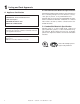
1 Listing and Code Approvals B. Non-Combustible Materials Specification A. Appliance Certification Material which will not ignite and burn. Such materials are those consisting entirely of steel, iron, brick, tile, concrete, slate, glass or plasters, or any combination thereof. MODELS: Soho-CE LABORATORY: Gastech Certification B.
2 Getting Started A. Design and Installation Considerations Heat & Glo balanced flue gas appliances are designed to operate with all combustion air siphoned from outside of the building and all exhaust gases expelled to the outside. No additional outside air source is required. CAUTION Check building codes prior to installation. • Installation MUST comply with local, regional, state and national codes and regulations.
3 Framing and Clearances WARNING Note: • Illustrations reflect typical installations and are FOR DESIGN PURPOSES ONLY. • Illustrations/diagrams are not drawn to scale. • Actual installation may vary due to individual design preference. Fire Risk Provide adequate clearance: • Around air openings • To combustibles • For service access Locate appliance away from traffic areas. A.
sulation. If the appliance is being installed on a cement slab, a layer of plywood may be placed underneath to prevent conducting cold up into the room. B. Constructing the Appliance Chase A chase is a vertical boxlike structure built to enclose the gas appliance and/or its flue system. Vertical flues that run on the outside of a building may be, but are not required to be, installed inside a chase. C. Clearances Construction of the chase may vary with the type of building.
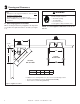
4 Termination Locations A. Flue Termination Minimum Clearances WARNING HORIZONTAL OVERHANG 61 cm MIN. Fire Risk. Explosion Risk. Maintain flue clearance to combustibles as specified. • Do not pack air space with insulation or other materials. Failure to keep insulation or other materials away from flue pipe may cause fire. 61 cm VERTICAL WALL LOWEST DISCHARGE OPENING TERMINATION CAP X 30 cm ROOF PITCH IS X/ 30 cm H (MIN.
M N P R Q (See Note 2) See Notes 3 & 4 V T V S Electrical Service S V D* V V = VENT TERMINAL X = AIR SUPPLY INLET A = 31 cm ....................clearances above grade, veranda, (See Note 1) porch, deck or balcony B = 31 cm ....................clearances to window or door that may be opened, or to permanently closed window. (Glass) D* = 31 cm ....................vertical clearance to unventilated soffit or to ventilated soffit located above the terminal 76 cm .....................
5 Flue Information and Diagrams A. Flue Table Key The abbreviations listed in this flue table key are used in the flue diagrams. First section (closest to appliance) of vertical length V2 Second section of vertical length H1 First section (closest to appliance) of horizontal length H2 Second section of horizontal length Vertical cm V1 21.6 cm WARNING Horizontal Fire Hazard. Explosion Risk. Asphyxiation Risk.
D. Flue Diagrams 1. Horizontal Termination One Elbow One Elbow V Minimum H Maximum Elbow only 76 cm 30 cm 91 cm 61 cm 1.8 m 91 cm 2.7 m 1.2 m 3.7 m 1.5 m 4.6 m H1 V + H Maximum = 11.9 m H Maximum = 4.6 m V1 Figure 5.3 Two Elbows Two Elbows V Minimum H1 + H2 Maximum Elbow only Not Allowed 30 cm 91 cm 61 cm 1.8 m 91 cm 2.7 m 1.2 m 3.7 m 1.5 m 4.6 m V + H1 + H2 Maximum = 11.9 m H1 + H2 Maximum = 4.6 m H2 H1 V1 Figure 5.
1. Horizontal Termination - (continued) Three Elbows Three Elbows V1 Minimum H1 Maximum V2 Minimum H2 Maximum 30 cm 61 cm 30 cm 61 cm 61 cm 1.2 m 61 cm 1.2 m 91 cm 1.8 m 91 cm 1.8 m 1.2 m 2.4 m 1.2 m 2.2 m V1 + V2 + H1 + H2 = Maximum = 11.9 m H1 + H2 Maximum = 4.6 m H2 V2 V1 H1 Figure 5.5 12 Heat & Glo • Soho-CE • 2111-900 Rev.
2. Vertical Termination V1 = 11.8 m Maximum No Elbow V1 Figure 5.6 Two Elbows Two Elbows V1 Minimum H Maximum Elbow only 46 cm 30 cm 91 cm 61 cm 1.2 m 91 cm 1.8 m 1.2 m 2.4 m 1.8 m 4.6 m V1 + V2 + H Maximum = 11.9 m H1 + H2 Maximum = 4.6 m V2 V1 H1 Figure 5.7 Heat & Glo • Soho-CE • 2111-900 Rev.
2. Vertical Termination - (continued) Three Elbows Three Elbows V1 Minimum H1 + H2 Maximum 30 cm 61 cm 61 cm 91 cm 91 cm 1.5 m 1.2 m 2.1 m 1.5 m 4.3 m V1 + V2 + H1 + H2 Maximum = 11.9 m H1 + H2 Maximum = 4.3 m V2 H2 H1 INSTALLED HORIZONTALLY Figure 5.8 14 Heat & Glo • Soho-CE • 2111-900 Rev.
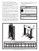
6 Flue Clearances and Framing A. Pipe Clearances to Combustibles B. Wall Penetration Framing WARNING 25.4 cm Fire Risk. Explosion Risk. Maintain flue clearance to combustibles as specified. • Do not pack air space with insulation or other materials. Failure to keep insulation or other materials away from flue pipe may cause fire. 7.62 cm TOP CLEARANCE B A 2.54 cm CLEARANCE AROUND VERTICAL SECTIONS 2.54 cm SIDE AND BOTTOM CLEARANCE A* B 96.5 cm 93.4 cm * Shows center of flue framing hole.
C. Vertical Penetration Framing WARNING Fire Hazard Keep loose materials or blown insulation from touching the flue pipe. • Hearth & Home Technologies requires the use of an attic shield. ATTIC ABOVE Installing the Ceiling Firestop A • Frame an opening 25.4 cm by 25.4 cm whenever the system penetrates a ceiling/ floor (see Figure 6.3). A steeply slanted roof may require an enlarged opening size in order to maintain proper flue pipe clearances.
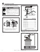
7 Appliance Preparation A. Securing and Leveling the Appliance The diagram shows how to properly position, level, and secure the appliance (see Figure 7.7). Nailing tabs are provided to secure the appliance to the framing members. • Place the appliance into position. • Level the appliance from side to side and front to back. • Shim the appliance, as necessary. It is acceptable to use wood shims. WARNING Fire Risk. • ALWAYS maintain specified clearances around the appliance.
8 Installing Flue Pipe A. Assembly of Flue Sections WARNING Fire Risk Exhaust Fumes Risk Impaired Performance of Appliance • Ensure flue components are locked together correctly. • Pipe may separate if not properly joined. Figure 8.1 Adding Flue Components Attach the First Flue Component to Starting Collars Install Support Brackets To attach the first flue component to the starting collars of the appliance: For Horizontal Runs - The flue system must be supported every 1.
B. Installing Firestops and Horizontal Termination Cap WARNING HEAT SHIELD TRIM HEAT SHIELD IF TOO LONG, ADD TO SHIELD IF TOO SHORT Fire Risk Exhaust Fumes Risk Impaired Performance of Appliance WALL SHIELD FIRESTOP (EXTERIOR) • Ensure flue components are locked together correctly. • Pipe may separate if not properly joined. For Horizontal Runs - Wall shield firestops are REQUIRED on both sides of a combustible wall through which the flue passes.
C. Install Roof Flashing and Vertical Termination Cap To install roof flashing see Figure 8.4. For installation of vertical termination cap see minimum flue heights for various pitched roofs (see Figure 8.4). To attach the vertical termination cap, slide the inner collar of the cap into the inner flue of the pipe section and place the outer collar of the cap over the outer flue of the pipe section.
Assembling and Installing Storm Collar CAUTION Sharp Edges • Wear protective gloves and safety glasses during installation. Connect both halves of the storm collar with two screws (see Figure 8.6). Wrap the storm collar around the exposed pipe section and align brackets. Insert a bolt (provided) through the brackets and tighten nut to complete storm collar assembly (see Figure 8.7). Slide the assembled storm collar down the pipe section until it rests on the roof flashing. Figure 8.
9 Gas Information A. Gas Pressure Requirements B. Gas Connection Pressure requirements for SOHO-CE fireplaces are shown in Table 1 below. Two taps are provided on the right hand side of the gas control for a test gauge connection to measure the inlet and outlet pressures. See Section 10: Maintaining and Servicing the Appliance.
10 Electrical Information A. Electronic Ignition System Wiring • This gas appliance is equipped with an electronic ignition system which operates on a 6 volt system. • The batteries are located within the ignition module which is located under the unit. A wiring diagram is shown in Figure 7.1. WARNING Shock hazard. • Replace damaged wire with type 105º C rated wire. • Wire must have high temperature insulation. • The battery pack requires four AA batteries (not included).
11 Finishing A. Facing Material WARNING Fire Risk. Finish all edges and fronts to clearances and specifications listed in manual. FINISH WALL MATERIAL MAY BE COMBUSTIBLE - TOP AND SIDES NON-COMBUSTIBLE ZONE 20.3 cm 0 cm 74 cm • Black metal appliance front may be covered with noncombustible material only. • Do NOT overlap combustible materials onto appliance front. • Install combustible materials up to specified clearances on top, front and side.
12 Appliance Setup A. Remove Shipping Materials D. Ember Placement Remove shipping materials from inside or underneath the firebox. B. Clean the Appliance Clean/vacuum any sawdust that may have accumulated inside the firebox or underneath in the control cavity. C. Accessories Install approved accessories per instructions included with accessories. See Service Parts List for appropriate accessories. Refer to Section 16. WARNING Explosion Risk. • Follow ember placement instructions in manual.
E. Positioning the Logs Log Assembly: LOGS-SOHOCE LOCATING TABS 2 3 1 Figure 12.3 Figure 12.2 CAUTION: Logs are fragile. Carefully remove the logs from the packaging. 1 2 1 Figure 12.4 Figure 12.5 Step 1. Place Log #1 (SRV2111-700) against rear right tab with its slot over center locating tab. Step 2 Place Log #2 (SRV2111-701) onto base pan such that Log #2 fits in groove of Log #1. Push it back against the left hand side locating tab. Ensure burner ports are not covered by logs.
F. Glass Assembly WARNING Handle glass doors with care. • Inspect the gasket to ensure it is undamaged. • Inspect the glass for cracks, chips or scratches. • Do NOT strike, slam or scratch glass. • Do NOT operate appliance with glass door removed, cracked, broken or scratched. • Replace glass door assembly as a complete appliance. Removing Glass Assembly Pull the two lower and two upper glass assembly latches out of the groove on the glass frame. Remove glass door from the appliance (see Figure 12.10).
13 Operating Instructions A. Before Lighting Appliance Before operating this appliance have a qualified technician: • Remove all shipping materials from inside and/or underneath the firebox. • Review proper placement of logs and mineral wool. • Check the wiring. • Check the air shutter adjustment. • Ensure that there are no gas leaks. • Ensure that the glass is sealed and in the proper position. • Ensure that the flow of combustion and ventilation air is not obstructed (flue terminations).
B. Lighting the Fireplace Electronic Ignition FOR YOUR SAFETY READ BEFORE LIGHTING WARNING: If you do not follow these instructions exactly, a fire or explosion may result causing property damage, personal injury or loss of life. A. This fireplace is equipped with • Do not touch any electric switch; do an electronic pilot ignition device not use any phone in your building. which automatically lights the • Immediately call your gas supplier burner. Do not try to light the from a neighbor’s phone.
C. After Appliance is Lit CAUTION Initial Break-in Procedure When you light the appliance, you may notice that it produces heat which does have an associated odor or smell. If you feel this odor is excessive it may require the initial three to four hour continuous burn on high followed by a second burn up to 12 hours to fully drive off any odor from paint and lubricants used in the manufacturing process. Condensation of the glass is normal.
14 Troubleshooting With proper installation, operation, and maintenance your gas appliance will provide years of trouble-free service. If you do experience a problem, this troubleshooting guide will assist a qualified service person in the diagnosis of a problem and the corrective action to be taken. This troubleshooting guide can only be used by a qualified service technician. A. Electronic Ignition System 1 Symptom No transmission, motor does not turn. Possible Causes A. Receiver must learn new code.
15 Maintaining and Servicing Appliance A. Maintenance Tasks Although the frequency of appliance servicing and maintenance will depend on use and the type of installation, a qualified service technician should perform an appliance check-up at the beginning of each heating season. WARNING CAUTION Risk of injury or property damage. Before servicing: • Turn off gas. • Turn off electricity to appliance. • Disable remote control, if one is present. • Ensure appliance is completely cooled.
Inspect Doors, Surrounds and Fronts Maintenance Tasks 1. Assess condition of screen and replace as necessary. Recommend addition of screen if one is not present. 2. Inspect for scratches, dents or other damage and repair as necessary. 3. Verify no obstructions to airflow through the louvers. 4. Verify maintenance of proper clearance to combustible household objects. Gasket Seal, Glass Assembly and Glass 1. Inspect gasket seal and its condition. 2.
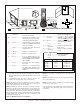
16 Reference Materials A. Appliance Dimension Diagram Dimensions are actual appliance dimensions. Use for reference only. For framing dimensions and clearances refer to Section 3. I J K L M ØN O C H D E Q GAS LINE ACCESS F ELECTRICAL ACCESS B P G A Appliance Dimensions Table Location Centimeter Location Centimeter A 74.0 J 29.2 B 64.3 K 29.2 C 94.5 L 27.9 D 74.2 M 14.2 E 10.5 N 16.8 F 5.6 O 94.0 G 11.5 P 9.6 H 83.2 Q 5.7 I 58.6 Figure 16.
SOHO-CE Service Parts List Beginning Manufacturing Date: 1-07 Ending Manufacturing Date: ______ Service Parts Diagram 4 5 6 9 7 8 10 11 Î 12 Log Set Assembly 2 3 Part number list on following page. 1 Heat & Glo • Soho-CE • 2111-900 Rev.
Î SOHO-CE B. Service Parts List IMPORTANT: THIS IS DATED INFORMATION. The most current information is located on your dealers’ VIP site. When ordering, supply serial and model numbers to ensure correct service parts.
SOHO-CE Service Parts Beginning Manufacturing Date: 1-07 Ending Manufacturing Date: ______ Valve Assembly Parts Diagram 1 2 3 4 5 15 6 14 13 7 8 9 12 11 10 IMPORTANT: THIS IS DATED INFORMATION. The most current information is located on your dealers’ VIP site. When ordering, supply serial and model numbers to ensure correct service parts.
C. Limited Lifetime Warranty LIMITED LIFETIME WARRANTY HEAT & GLO GAS APPLIANCE PRODUCTS BASIC ONE-YEAR WARRANTY. HEAT & GLO, a brand of HEARTH & HOME TECHNOLOGIES INC., located at 20802 Kensington Boulevard, Lakeville, MN 55044, (“HEAT & GLO”) warrants to the original owner that your new HEAT & GLO Gas Appliance (the “Product”) will be free from defects in materials and workmanship for a period of one year from the date of installation.
D. Contact Information Heat & Glo, a brand of Hearth & Home Technologies Inc. 20802 Kensington Boulevard, Lakeville, MN 55044 USA www.heatnglo.com Please contact your Heat & Glo dealer with any questions or concerns. For the location of your nearest Heat & Glo dealer, please visit www.heatnglo.com.