R SAPPHIRE DIRECT VENT ROOM HEATER Owner’s Manual Installation and Operation Model: Quartet Front 839-1390 839-1440 839-1460 SAPPH-D-CSB SAPPH-D-CWL Solitaire Front Tested and Listed by Portland Oregon USA O-T L C US OMNI-Test Laboratories, Inc. CAUTION DO NOT DISCARD THIS MANUAL • Important operating and • Read, understand and • Leave this manual with follow these instructions maintenance instructions party responsible for use for safe installation and included. and operation. operation.
and Welcome to the Quadra-Fire Family! Hearth & Home Technologies welcomes you to our tradition of excellence! In choosing a Quadra-Fire appliance, you have our assurance of commitment to quality, durability, and performance. of our stoves, inserts and fireplaces. And yet we are oldfashioned when it comes to craftsmanship. Each appliance is meticulously fabricated and gold and nickel surfaces are hand-finished for lasting beauty and enjoyment.
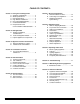
- TABLE OF CONTENTS Section 1: Listing and Code Approvals A. Appliance Certifications ......................4 B. Glass Specifications ............................4 C. BTU Specifications ..............................4 D. High Altitude Installations ....................4 E. Non-Combustible Materials .................4 F. Combustible Materials ........................4 G. Requirements for the Commonwealth of Massachusetts ......5 Section 2: Getting Started A. Design & Installation Considerations ...............
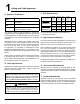
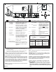
1 Listing and Code Approvals C. BTU Specifications A. Appliance Certification Maximum Input BTU Minimum Input BTU Orifice Size (DMS) *Steady State Efficiency % **P.4 % TOP VENT: Sapphire (NG) Sapphire (LP) 30,000 21,000 36 84 64 30,000 24,500 52 82 65 REAR VENT: Sapphire (NG) Sapphire (LP) 26,000 18,000 41 84 64 26,000 20,000 53 82 65 Model (US or Canada) MODEL: Sapphire LABORATORY: OMNI Test Laboratories, Inc. 061-S-19b-5 TYPE: Direct Vent Gas Heater STANDARD: ANSI Z21.
NOTE: The following requirements reference various Massachusetts and national codes not contained in this document. G.
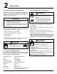
2 Getting Started A. Design & Installation Considerations Quadra-Fire direct vent gas appliances are designed to operate with all combustion air siphoned from outside of the building and all exhaust gases expelled to the outside. No additional air source is required. CAUTION Check building codes prior to installation. • Installation MUST comply with local, regional, state and national codes and regulations.
3 Appliance Location and Clearances NOTE: · Illustrations reflect typical installations and are FOR DESIGN PURPOSES ONLY. · Illustrations/diagrams are not drawn to scale. · Actual installation may vary due to individual design preference. WARNING Fire Risk Provide adequate clearance: • Around air openings • To combustibles • For service access Locate appliance away from traffic areas. A.
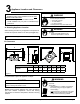
4 Termination Locations A. Vent Termination Minimum Clearances 20 in. (508mm) (minimum) to Perpendicular Wall (Gas Only) WARNING Fire Risk. Explosion Risk. Maintain vent clearance to combustibles as specified. • Do not pack air space with insulation or other materials. Failure to keep insulation or other materials away from vent pipe may cause fire. HORIZONTAL OVERHANG 2 FT. MIN. 20 IN. VERTICAL WALL LOWEST DISCHARGE OPENING TERMINATION CAP X 12 Measure vertical clearances from this surface.
M N P G R v A D H Q (See Note 2) E v V B L v v F v U.S. (3 FT) B B v T V v I M v A V = VENT TERMINAL A B D* = 12 inches ............. clearances above grade, veran(See Note 1) da, porch, deck or balcony = 12 inches ............ clearances to window or door that may be opened, or to permanently closed window. (Glass) = 18 inches ............. vertical clearance to unventilated soffit or to ventilated soffit located above the terminal *30 inches ............
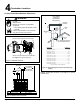
5 Vent Information A. Venting Components B. Use of Elbows In order to comply with applicable codes and product warranties, use only following venting components: • • • • • CAUTION Hearth & Home Technologies (HHT) Simpson Dura-Vent (SDV) Selkirk AmeriVent Security Secure Vent ALL vent configuration specifications MUST be followed. • This product is tested and listed to these specifications. • Appliance performance will suffer if specifications are not followed.
D. How to Use the Vent Graph E. Venting Guidelines 1. Notes: The maximum horizontal vent run is 15 ft. (5m) when the vertical vent rise is 10 ft. (3m). The minimum horizontal vent run is 11 in. (279mm). Minimum wall thickness is 4 in. (102mm). Maximum wall thickness is 20 in. (508mm). Horizontal sections require a 1/4 in. (6mm) rise for every 12 in. (305mm) of horizontal travel. Exterior Vent Diameter = 6-5/8 in. (168mm); Inner Vent Diameter = 4 in. (101mm).
F. Horizontal Termination Type A - WARNING Up & Out Installations for Top Vent Configurations Fire Hazard. Exhaust Fume Risk. Impaired Performance of Appliance. • Ensure vent components are locked together correctly. 90º Elbow • Pipe may separate if not properly joined. Pipe Length Wall Thimble Wall Thimble Cover Temination Cap Pipe Length Step 2. Direct vent pipe is designed with a locking connection.
Step 3. For installations using a round support box/wall thimble (check pipe manufacturer's instructions), mark the wall for a 10 in. x 10 in. (254mm x 254mm) square hole. The center of the square hole should line up with the center line of the horizontal pipe, as shown in Figure 5.5. Cut and frame the hole in the exterior wall where the vent will be terminated. If the wall being penetrated is constructed of noncombustible material, i.e. masonry block or concrete, a 7 in.
1/4 in. (6mm) 8 in. Fold Strap Here (203mm) 7 in. (178mm) 7 in. (178mm) Sheet Metal Screw 6 in. (152mm) Wall Thimble Wall Thimble Cover/Ceiling Firestop as Required by Local Jurisdiction Strap Figure 5.7 Figure 5.9 (NOTE: Some termination caps may cause the vent pipe to be off center on flashing). Ensure that proper clearances to combustible materials are maintained.
G. Vertical Termination 1. Direct Vent Pipe Vertical Termination Cap Storm Collar Flashing 35 ft. (11m) Maximum Firestop Support Box Pipe Length Figure 5.11 Figure 5.10 Step 1. Check the installation instructions for required 1 in. (25mm) clearances (air space) to combustibles when passing through ceilings, walls, roofs, enclosures, attic rafters, or other nearby combustible surfaces. See page 16, Figure 5.15.
Step 3. To install the round support box/wall thimble cover in a flat ceiling, cut a 10 in. (254mm) square hole in the ceiling, centered on the hole drilled in Step 2. Frame the hole as shown in Figure 5.13. Shingles overlap on top edge of flashing CAP AND STORM COLLAR NOT SHOWN FOR CLARITY Ceiling Joists Framing Figure 5.14 Figure 5.13 1 - 1/2 in. (38mm) Long Wood Screws Step 4. Assemble the desired lengths of pipe and elbows necessary to reach from the appliance up through the round support box.
Step 9. Twist-lock the vent cap and seal. Note: For multi-story vertical installations, a ceiling firestop is required at the second floor, and any subsequent floors (Figure 5.16). The opening should be framed to 10 in. x 10 in. (254mm x 254mm) inside dimensions, in the same manner as shown in Figure 5.13, page 16. Nails Ceiling Firestop Minimum 1 in. (24mm) Clearance Minimum 1 in. (24mm) Clearance Minimum 1 in. (24mm) Clearance Minimum 1 in. (24mm) Clearance Figure 5.16 WARNING Fire Risk.
2. Cathedral Ceiling Step 1. Follow installation Steps 1 and 2 under vertical installation section, page 15. Step 2. Using the plumb-bob, mark the center line of the venting system on the ceiling, and drill a small hole through the ceiling and roof at this point. From the roof, locate the drill hole and mark the outline of the cathedral ceiling support box. Step 3. Remove shingles or other roof covering as necessary to cut the rectangular hole for the support box. Cut the hole 1/8 in.
3. Class A Metal Chimney Termination Cap Top Adaptor Flashing Step 4. Pass the flex pipe down through the center of the chimney system, and center the top adapter on the top of the chimney pipe. Drill four 1/8 in. (3mm) diameter holes through the top adapter, and into the chimney top. Ensure that you are drilling into the metal on the chimney. Twist lock the high wind termination cap onto the top adapter (Figures 5.21 and 5.22). Existing Metal Chimney System 4 in.
4. Existing Masonry Chimney Type A - Up & Out Installations for Top Vent Configurations Type B - Hearth Rear Vent Installations for Use With Rear Vent Kit (see Section 12 for conversion kit and venting components.) Termination Cap Top Adapter Retro Connector Chimney Liner Termination Cap Flashing 4 in. (102mm) Flex Liner Direct Vent Pipe 3 in. (76mm) Flex Liner Co-Axial to Co-Linear Connector 90º Elbow Pipe Length Optional Showing two 30 ft.
CAUTION Cut and bend flashing as needed to fit Ensure that existing chimney is functionally sound and clean. • Have inspection done by qualified chimney sweep or professional installer BEFORE converting to direct vent appliance. Step 1. Before cutting any holes, assemble the desired sections of direct vent pipe to determine the center of the masonry penetration. Step 2. Once the center point of the penetration has been determined, cut a 6 in. (152mm) diameter hole in the masonry.
Flex Liner 6 in. (152mm) diameter opening in masonry wall Flex Coupler Sheet Metal Screws Retro Connector (3) Masonry Bolts (Not included) Figure 5.26 Figure 5.28 Step 8. Secure the top adapter to the flashing. Use three sheet metal screws through the side of the top adapter into the flange on the flashing (Figure 5.27). Twist lock the high wind termination cap on to the top adapter. High Wind Termination Cap Step 10.
6 Gas Information A. Fuel Conversions Before making gas connections ensure that the appliance being installed is compatible with the available gas type. Any natural or propane gas conversions necessary to meet the appliance and locality needs must be made by a qualified technician using Hearth & Home Technologies specified and approved parts. 1.
Replace pilot injector with the one supplied in the conversion kit (#35 for Propane, #62 for Natural Gas). 2. Valve Regulator Replacement WARNING NOTE: The injector is ONLY replaced if you are converting to another gas. It is not replaced for a change from top to rear vent. Fire Risk. Explosion Risk. • Disconnect any electrical cords and turn off gas supply to unit before proceeding if converting fuel on an appliance already fully installed. Replace pilot hood, snapping into position.
B. Gas Pressures E Screws Proper input pressures required for optimum appliance performance, gas line sizing requirements need to be followed from NFPA51. D WARNING Rubber Gasket Identification Label F Ensure that the rubber gasket (D) is properly positioned and install the new HI/LO pressure regulator assembly to the valve using the new screws (E) supplied with the kit. Tighten screws securely. (Reference torque = 25 in./lb.
C. Gas Connection WARNING NOTE: Have the gas supply line installed in accordance with local building codes, if any. If not, follow ANSI Z223.1. Installation should be done by a qualified installer approved and/or licensed as required by the locality. (In the Commonwealth of Massachusetts, installation must be performed by a licensed plumber or gas fitter.
7 Electrical Information A. Recommendation for Wire See B5 below for recommended maximum lead length (two wire) when using wall thermostat/switch. NOTE: This appliance must be electrically wired and grounded in accordance with local codes or, in the absence of local codes, with National Electric Code ANSI/NFPA 70-latest edition or the Canadian Electric Code, CSA C221.1. Ensure the thermostat is mounted level for accurate readings. 9.
Thermopile Gas Pilot Ignitor Thermocouple Ignitor Red 28 in. (711mm) ON/OFF Switch Red 28 in. (711mm) Valve Figure 7.1 CAUTION CAUTION Label all wires prior to disconnection when servicing controls. Wiring errors can cause improper and dangerous operation. Verify proper operation after servicing. Page 28 Shock hazard. • Replace damaged wire with type 105O C rated wire. • Wire must have high temperature insulation.
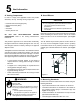
8 Appliance Setup A. Remove Shipping Materials Remove shipping materials from inside or underneath the firebox. B. Top and Rear Vent Conversion KIT CONTENTS: Rear vent grill; .096 NG orifice; .059 LP orifice; Rear Vent Cover Plate, Top Grill Cover Plate TOOLS REQUIRED: Power drill; #2 Phillips bit; 5/32 in. Allen wrench; 5/8 in. open end wrench; high-temp silicone sealant (optional.) Remove the rear outer flue cover plate (with the damper adjustment plate attached).
Figure 8.4 Install the inner flue collar on rear of appliance, with damper rod pointing up. A dab of high temperature silicone on the gasket will help gasket adhere to the appliance. Install the inner collar and outer flue collar on the rear of the appliance. Figure 8.7 Install the rear vent cover plate, supplied iwth the kit, on the back shield. Reinstall the cast insert piece in the top of the appliance. NOTE: A grill cover plate is shipped with the appliance.
C. Grille Cover Plate Installation Top grill cover is shipped with the appliance and is an optional use item. It may be used with rear or top venting. Primarily its purpose is to hide the interior of the top of the appliance from being viewed through the top grill piece. Its use will also increase the efficiency of the blower, if a blower is installed on the appliance. Remove burner by sliding the shutter to the right, lifting up the left side of the burner and sliding it the the left. Figure 8.
E. Front Installation Fronts are shipped attached to the face. INSTALLATION AND REMOVAL INSTRUCTIONS FOR QUARTET AND SOLITAIRE FACE OPTIONS. Quartet Front Solitaire Front Place a washer on the top of the door hinge. Line up the hole in the door hinge and the washer with the hole in the hinge box of the face. Place a gold-plated hinge pin in the hole to secure. Figure 8.15 Quartet Door Alignment Doors are properly aligned at the point of manufacture.
F. Hearth Legs Installation NOTE: HEARTH LEGS CANNOT BE USED IF A BLOWER IS INSTALLED AS THERE WILL NOT BE ENOUGH CLEARANCE. Refer to Section 12 for specific color part numbers. Hearth legs will allow three additional inches of clearance. Be sure to calculate this distance correctly if necessary to cut wall hole to install horizontally. Refer to Dimensions on in Section 12. Set the rear log on the three locator pins in the back of the firebox. Figure 8.19 To change legs, use a 1/2 in.
J. Blower Installation H. Mineral Wool FROM THE KIT YOU WILL NEED: Blower motor; snap disc bracket with wire harness; rheostat, rheostat nut; knob; screws; 1 zip-tie. WARNING Explosion Risk. • Follow ember placement instructions in manual. • Do NOT place embers directly over burner ports. • Replace ember material annually. TOOLS REQUIRED: #2 Phillips head bit; hand drill; 11/16 in. wrench. Improperly placed embers interferes with proper burner operation. Figure 8.
Use two screws to connect the snap disc bracket to the blower mounting bracket. Figure 8.24 Route the wires from the snap disc to the right, upper edge of the blower. Insert the rheostat control into its opening from beneath the control panel. Fit the rheostat nut on top and tighten the nut using an 11/16 in. wrench. Attach the black knob. Figure 8.25 Gather any excess in the wiring and zip-tie to the switch wires and piezo wire at the rear of the appliance.
RHEOSTAT F M M F 34 in. (864mm) BLACK 34 in. (864mm) WHITE SNAP DISC 4 in. (102mm) WHITE F F 6 in. (152mm) BLACK F M F M M F CORD BLOWER Figure 8.
K. Damper Adjustment FOR TOP OR REAR VENT INSTALLATIONS See vent graph for recommendations on page 11 before you begin your adjustment. If your installation falls within the range of the gray shaded area of graph, it may be necessary to make an adjustment to the vertical damper to improve the flame appearance in your appliance. Damper Adjustment Plate Make adjustment until flame size and activity suits your personal preference, and then retighten screws on adjustment control.
9 Operating Instructions A. Before Lighting Appliance Read this entire manual prior to using the appliance. Failure to follow the instructions may result in property damage, bodily injury, or even death. • Remove all shipping materials from inside and/or underneath the firebox. • Review proper placement of logs, mineral wool. • Check the wiring. • Check the baffle adjustment. • Ensure that there are no gas leaks. • Ensure that the glass is sealed and in the proper position.
C. Lighting Appliance FOR YOUR SAFETY READ BEFORE LIGHTING WARNING: If you do not follow these instructions exactly, a fire or explosion may result causing property damage, personal injury or loss of life A. This appliance has a pilot that must be lit manually. When lighting the pilot, follow these instructions exactly. B. BEFORE LIGHTING, smell around the appliance area for gas. Be sure to smell next to the floor because some gas is heavier than air and will settle on the floor.
D. After Appliance is Lit CAUTION Initial Break-in Procedure When you light your appliance, you may notice that it produces heat which does have an associated odor or smell. If you feel this odor is excessive it may require the initial three to four hour continuous burn on high followed by a second burn up to 12 hours to fully drive off any odor from paint and lubricants used in the manufacturing process. Condensation on the glass is normal.
10 Troubleshooting With proper installation, operation, and maintenance your gas appliance will provide years of trouble-free service. If you do experience a problem, this troubleshooting guide will assist a qualified service person in the diagnosis of a problem and the corrective action to be taken. This troubleshooting guide can only be used by a qualified service technician. Symptom 1. After repeated triggering of the piezo button, the spark ignitor will not light the pilot. 2.
Symptom 3. (Continued) Possible Cause Corrective Action c. Defective valve. Turn the valve knob to the ON position. Place the ON/OFF switch in the ON position. Check the millivolt meter at the thermopile terminals. The millivolt meter should read greater than 125mV. If the reading is acceptable, and if the burner does not come on, replace the gas valve. d. Plugged burner orifice. Check the burner orifice for stoppage. Remove stoppage. e. Wall switch or wires are defective.
11 Maintaining and Servicing Appliance Although the frequency of your appliance servicing and maintenance will depend on use and the type of installation, a qualified service technician should perform an appliance check-up at the beginning of each heating season. CAUTION Handle glass assembly with care. NOTE: Clean glass after initial 3-4 hours operation. Longer operation without cleaning glass may cause a permanent white film on glass. WARNING Risk of injury or property damage.
A Maintenance Tasks Inspect Doors Maintenance Tasks 1. Inspect for scratches, dents or other damage and repair as necessary. 2. Verify no obstructions to air flow. 3. Verify maintenance of proper clearance to combustible household objects. Gasket Seal, Glass Assembly and Glass 1. Inspect gasket seal and its condition. 2. Inspect glass for scratches and nicks that can lead to breakage when exposed to heat. 3. Confirm there is no damage to glass or glass frame, Replace as necessary. 4.
12 Reference Materials A. Appliance Dimension Diagram Dimensions are actual appliance dimensions. Use for reference only. For clearances refer to Section 3. A D E B F C CL G CL J L I K REAR VENT H NOTE: If appliance is equipped with Hearth Legs Kit, center-line dimension is reduced by 3 in. (76mm). TOP VENT Figure 12.
B. Vent Components Diagram 6-3/8 in. (162mm) 6-1/2 in. (165mm) 9-1/4 in. (235mm) 6-1/2 in. (165mm) 6-3/8 in. (162mm) 6-5/8 in. (168mm) 9-5/8 in. (244mm) SLP45-BK 6-5/8 in. (168mm) 9-5/8 in. (244mm) SLP90M 17-24 in. (432-610mm) 6-1/2 in. (165mm) 11-3/4 in. (298mm) SLP12AM 5-3/4 in. (146mm) 6-5/8 in. (168mm) SLP12M SLP6M 47-3/4 in. (1213mm) 35-3/4 in. (908mm) 23-3/4 in. (603mm) 12-17 in. (305-432mm) 3-3/4 in. (95mm) SLP4M SLP6AM SLP24M SLP36M SLP48M 4 in. (102 mm) inner pipe 6-5/8 in.
C.
Description 45° Elbow, Swivel, Black 90° Elbow, Galvanized 90° Elbow, Black HHT SL-P M= Multi Pack (6) Simpson ® Dura-Vent DirectVent Pro Selkirk ® Direct-Temp Amerivent ® Direct Security ® Secure Vent - 46DVA-E45B - - SV4EB45 SLP90M See Swivel 4DT-EL905 4D90LS - SLP90-BK See Swivel 4DT-EL90SB 4D90LBS SV4EBR90 90° Elbow, Swivel, Galvanized - 46DVA-E90 - - SV4E90 90° Elbow, Swivel, Black - 46DVA-E90B - - SV4EB90 Adjustable Flashing, 0/12-6/12 SLP-RF6M 46DVA-F6 4DT-AF6 4D
R SAPPHIRE Service Parts List D. Beginning Manufacturing Date: 4-24-02 Ending Manufacturing Date: (NG, LP) Exploded Parts Diagram 14 20 19 13 15 12 21 16 22 17 11 18 8 10 9 7 6 3 5 4 1 Item # September 1, 2008 Description 2 Item # Description 1 Refractory, Metal 12 Igniter, Piezo 2 Log Support, Rear 13 Switch, Rocker, ON/OFF 3 Burner Support 14 Knob, Rheostat 4 Bulkhead 15 Set Collar, 1/4 in.
R D. Service Parts (cont’d.) (NG, LP) Exploded Parts Diagram SAPPHIRE Beginning Manufacturing Date: 5-19-05 Ending Manufacturing Date: IMPORTANT: THIS IS DATED INFORMATION. The most current information is located on your dealer's VIP site. When ordering, supply serial and model numbers to ensure correct service parts.
R D. Service Parts (cont’d.) (NG, LP) Exploded Parts Diagram Beginning Manufacturing Date: 5-19-05 Ending Manufacturing Date: IMPORTANT: THIS IS DATED INFORMATION. The most current information is located on your dealer's VIP site. When ordering, supply serial and model numbers to ensure correct service parts.
R D. SAPPHIRE Service Parts (cont’d.) (NG, LP) Exploded Parts Diagram Beginning Manufacturing Date: 5-19-05 Ending Manufacturing Date: IMPORTANT: THIS IS DATED INFORMATION. The most current information is located on your dealer's VIP site. When ordering, supply serial and model numbers to ensure correct service parts. Item # 9 Part Description Alphabetical Order SKU Top See page 52 Touch-up Paint, Matte Black (4oz.
F.
G. Warranty Policy Hearth & Home Technologies LIMITED WARRANTY Hearth & Home Technologies (“HHT”) and its respective brands extends the following warranty for HHT gas, wood, pellet and electric appliances purchased from an authorized HHT dealer and installed in the United States of America or Canada. Warranty starts with date of purchase by the original owner (End User) except as noted for replacement parts.
Hearth & Home Technologies LIMITED WARRANTY (Cont’d) HHT’s obligation under this warranty does not extend to damages resulting from: (1) installation, operation or maintenance of the appliance not in accordance with the installation instructions; operating instructions and the listing agent identification label furnished with the appliance; (2) installation which does not comply with local building codes; (3) shipping, improper handling, improper operation, abuse, misuse, accident or unworkmanlike repairs
H. Contact Information R CONTACT INFORMATION: Hearth & Home Technologies 1445 North Highway Colville, WA 99114 Division of HHT INDUSTRIES Please contact your Quadra-Fire dealer with any questions or concerns. For the number of your nearest Quadra-Fire dealer please visit our web site at www.quadrafire.com CAUTION Do NOT discard this manual. • Important operating and maintenance instructions included. • Read, understand and follow these instructions for safe installation and operation.