
Universal Remote User Manual

9
Hearth & Home Technologies • RCTS-MLT Instructions • 100-920 Rev. D • 10/10
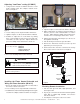
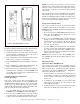
7. Set the SET temperature to at least 2º F (1º C) below
the room temperature and the system fl ame will extin-
guish. Thereafter, it should continue to cycle on and
off thermostatically approximately every two minutes
as the ROOM temperature changes, but only when
the temperature differential between ROOM and SET
temperatures differs at least 2º F (1º C). The 2º F dif-
ferential is the factory setting.
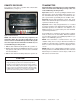
Timer Operation
The countdown timer will operate in either the manual ON
or THERMO mode. Once the fi replace system is in an
operating mode, set the countdown timer to turn off in 15
minutes. The timer function will allow operation to continue
until the “countdown time” on the LCD screen expires. After
15 min. elapses, the system should turn off.
This REMOTE CONTROL SYSTEM is warranted for 12
months from the date of purchase or installation to the original
purchaser to be free from defects in materials and workman-
ship. Damage to the SYSTEM caused by accident, misuse,
abuse, or installation error whether performed by a contractor,
service company, or owner, is not covered by this warranty.
Seller will not be responsible for labor charges and/or damage
incurred in installation, repair, replacement or for incidental or
consequential damages. Batteries and any damage caused
by them are not covered by this warranty.
Some states, provinces, and nations do not allow exclusion
or limitations of incidental or consequential damages, so the
above limitations or exclusions may not apply. This warranty
gives you specifi c legal rights. You may have other rights that
vary by state, province or nation.
GENERAL INFORMATION
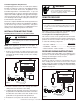
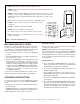
Transmitter Wall Bracket
The transmitter can be hung on a wall using the bracket
provided. Locate the bracket on an inside wall suffi ciently
far away from direct sources of heat such as a fi replace,
incandescent lighting, or sunlight so it detects ambient
room temperatures, not a single heat source. If the bracket
is installed on a solid wood wall, drill 1/8” pilot holes and
install with the screws provided. If it is installed on a plas-
ter/wallboard wall, fi rst drill two 1/4” holes into the wall,
then use a hammer to tap in the two plastic wall anchors
fl ush with the wall, then install the screws provided.
Battery Life
Life expectancy of the batteries in the transmitter should
be at least 12 months. Check batteries annually. When the
transmitter no longer operates the remote receiver from a
distance it did previously (i.e., the transmitter’s range has
decreased) the batteries should be checked.
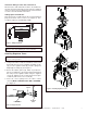
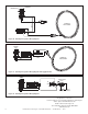
Service Parts List
Limited Warranty
DESCRIPTION SERVICE PART NO.
3-PRONG ADAPTOR HTI -18-006
SOLENOID-110 VOLT HI/LO 4021-379
TRANSMITTER WALL HOLDER HTI -16-006
BATTERIES-TRANSMITTER HTI -14-006
RECEIVER HTI -13-006
TRANSMITTER (RCT-MLT-HNG) HTI -12-006-HNG
TRANSMITTER (RCT-MLT-HTL) HTI -12-006-HTL
TRANSMITTER (RCT-MLT-QF) HTI-12-006-QF
HARDWARE PACKAGE HTI -11-006
Specifi cations
Transmitter
Power Requirements: 3V 2 ea.; AAA 1.5V, Alkaline
Operating Frequency: 303.8 MHZ
FCC ID No.’s: K9L300ITX
Canadian ISC ID No.’s: 2439 102 760
Remote
Power Requirements: 110-120 VAC; 60Hz
Operating Frequency: 303.8 MHZ
FCC ID No.’s: K9L3003RX
Canadian ISC ID No.’s: 2439 102 760A