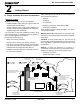
R MT VERNON PELLET INSERT ADVANCED ENERGY (AE) Owner’s Manual Installation and Operation Tested and Listed by Portland Oregon USA O-T L C US OMNI-Test Laboratories, Inc. Models: MTVERNINSAE-MBK MTVERNINSAE-PMH MTVERNINSAE-CSB MTVERNINSAE-CWL NOTICE • Important operating and • Read, understand and • Leave this manual with follow these instrucparty responsible for use maintenance instructions for safe installaand operation. tions included. tion and operation.
R Mt. Vernon Pellet Insert (AE) Hearth & Home Technologies welcomes you to our tradition of excellence! In choosing a Quadra-Fire appliance, you have our assurance of commitment to quality, durability, and performance. our stoves, inserts and fireplaces. And yet we are old-fashioned when it comes to craftsmanship. Each unit is meticulously fabricated and surfaces are hand-finished for lasting beauty and enjoyment. Our pledge to quality is completed as each model undergoes a quality control inspection.
R Mt. Vernon Pellet Insert (AE) TABLE OF CONTENTS Section 7: Appliance Set-Up (Cont’d) Section 1: Listing and Code Approvals A. B. C. D. E. E. F. G. H. Appliance Certifications ......................4 Mobile Home Approved ......................4 Glass Specifications ............................4 Electrical Rating ..................................4 BTU & Efficiency Specifications ..........4 Panel & Cast Trim Set ........................20 Panel & Trim Set, Basic ......................
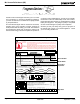
R Mt. Vernon Pellet Insert (AE) 1 Listing and Code Approvals E. BTU & Efficiency Specifications A. Appliance Certification MODEL: Mt. Vernon Pellet Insert AE Emissions Rating: EPA Compliant LABORATORY: OMNI Test Laboratories, Inc *BTU Output: 14,620 - 60,200 REPORT NO. 061-S-69-6 Efficiency: 81.4% - 83.
R 2 Mt. Vernon Pellet Insert (AE) Getting Started A. Design, Installation & Location Considerations Since pellet exhaust can contain ash, soot or sparks, you must consider the location of: 1. Appliance Location • Windows NOTICE: Check building codes prior to installation. • Installation MUST comply with local, regional, state and national codes and regulations.
R Mt. Vernon Pellet Insert (AE) B. Locating Your Appliance & Chimney E. Negative Pressure Location of the appliance and chimney will affect performance. WARNING! Risk of Asphyxiation! Negative pressure can cause spillage of combustion fumes and soot. • • Install through the warm airspace enclosed by the building envelope. This helps to produce more draft, especially during lighting and die-down of the fire. Penetrate the highest part of the roof. This minimizes the effects of wind loading.
R Mt. Vernon Pellet Insert (AE) F. Fire Safety G. Tools And Supplies Needed To provide reasonable fire safety, the following should be given serious consideration: • Install at least one smoke detector on each floor of your home. • Locate smoke detector away from the heating appliance and close to the sleeping areas. • Follow the smoke detector manufacturer’s placement and installation instructions and maintain regularly. • Conveniently locate a Class A fire extinguisher to contend with small fires.
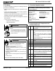
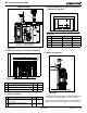
R Mt. Vernon Pellet Insert (AE) 3 Dimensions and Clearances A. Appliance Dimensions 32 in. (812mm) 23-7/8 in. 8-1/8 in. (606mm) (206mm) 15 in. (382mm) CL 2-3/8 in. (59mm) 29-3/4 in. (756mm) 23-7/8 in. (605mm) 13-1/8 in. (333mm) 26-1/4 in. (667mm) 28-1/8 in. (714mm) Figure 8.1 - Top View Figure 8.2 - Side View 36-5/8 in. (929mm) 33 in. (838mm) 34-7/8 in. (886mm) 46-1/8 in. (1171mm) 50 in. (1270mm) Figure 8.3 - Front View with Basic Surround Panel Set Page 8 Figure 8.
R Mt. Vernon Pellet Insert (AE) B. Clearance To Combustibles, UL and ULC Built-in Unit - Rear Vent A D C B B C E 0 inch Clearance To Exposed Section And Face Trim Figure 9.
R Mt. Vernon Pellet Insert (AE) E. Minimum Opening for Masonry and Zero Clearance Fireplaces Built-In Vertical H G in mm F I in mm Figure 10.3 in mm se two degree elbows to clear heat shield and hopper Location Inches Millimeters F Rear Width 24 610 G Depth 15 381 H Height 23-7/8 606 I Front Width 34 864 Figure 10.1 C. Masonry and Zero Clearance Fireplaces F. Mantel Projections Side Wall J Face Trim Mantel K B A C E D Figure 10.
R Mt. Vernon Pellet Insert (AE) G. Removing Metal Floor of Factory-Built Firebox • • • The firebrick (refractory), glass doors, screen rails, screen mesh and log grates can be removed from a factory-built firebox in order to gain minimum insert opening requirements. Any smoke shelves, shields and baffles may be removed from a factory-built firebox if attached with mechanical fasteners.
R Mt. Vernon Pellet Insert (AE) 4 Vent Information A. Venting Termination Minimum Requirements V N V Inside N orner Electrical Ser ice N V N V G V A D O V L P C V B FIXED CLOSED V F FIXED CLOSED OPEN V B OPEN V V V Termination Cap G X Air Supply Inlet M I A B B Figure 12.1 H E G Gas Meter V X J or Restricted Area All minimum clearances are listed with an Outside Air Kit (OAK) installed, unless otherwise noted in table below. A 12 in.
R Mt. Vernon Pellet Insert (AE) B. Chimney and Exhaust Connection 1. Chimney & Connector: Use 3 or 4 inch (76-102mm) WARNING diameter type "L" or "PL" venting system. It can be vented vertically or horizontally. Fire Risk. • Only LISTED venting components may be used. 2. Mobile Home: Approved for all Listed pellet vent. Use Listed double wall flue connector. A Quadra-Fire Outside Air Kit must be used with manufactured home installations. • NO OTHER vent components may be used.
R Mt. Vernon Pellet Insert (AE) D. Pipe Selection Chart WARNING The chart will help you in determining proper venting size according to the equivalent feet of pipe calculated in the Vent Termination Calculaltion Table and the altitude above sea level of this installation. See Figure 14.1. Fire Risk. Locate the calculated equivalent feet of pipe on the vertical left side of the chart. Move to the right horizontally on the chart until you reach your altitude above sea level.
R 5 Mt. Vernon Pellet Insert (AE) Venting Systems A. Direct Connect Without Outside Air B. Direct Connect With Outside Air NOTE; Use metal plate around exhaust vent pipe and seal all edges with non-flammable insulation such as fiberglass, mineral wool or ceramic material. Do not use high temperature caulking materials to seal any edge to prevent future serviceability. Outside Air through Rear Wall Figure 15.2 Figure 15.
R Mt. Vernon Pellet Insert (AE) CAUTION C. Full Reline With Outside Air NOTE: Check clearances carefully for this type of installation to ensure adequate room for outside air venting. NOTE: In Canada only a full reline is allowed per ULC S628, ORD ULC C1482-M1990. Check building codes prior to installation. • Installation MUST comply with local, regional, state and national codes and regulations.
R 6 Mt. Vernon Pellet Insert (AE) Mobile Home A. Mobile Home Installation You must use a Quadra-Fire Outside Air Kit for installation in a mobile home. 1. An outside air inlet must be provided for the combustion air and must remain clear of leaves, debris, ice and/or snow. It must be unrestricted while the appliance is in use to prevent room air starvation which causes smoke spillage. Smoke spillage can also set off smoke alarms. 2. The combustion air duct system must be made of metal.
R Mt. Vernon Pellet Insert (AE) 7 Appliance Set-Up A. Leveling System B. Outside Air Kit Instructions The leveling bolts are located on the sides of the appliance, front and rear. To access the bolts, remove the front access panels. Reach in and turn the bolt to the desired height to level the appliance. Included in Kit: 2 wire ties, 1 collar assembly, 1 termination cap assembly, 1 trim ring, fasteners. NOTE: 3 INCH ALUMINUM FLEX PIPE NOT INCLUDED.
R Mt. Vernon Pellet Insert (AE) C. Hearth Support Included in Kit: (1) bottom, (1) trim front, (2) trim sides, (2) trim extensions 7. Place the assembled hearth support under the insert. Lower the leveling bolts if necessary to keep the insert level. Tools Needed: Phillips head screw driver, measuring tape, gloves 8. Open the door and attach the hearth support to the insert. There are 9 attachment holes. Figure 19.3. 1.
R Mt. Vernon Pellet Insert (AE) F. Panel & Trim Set, Basic E. Panel and Trim Set - Cast Included in Panel Kit: (2) side panels, left and right; (1) panel top; (1) fastener package. Included in Panel & Trim Kit: (2) corner brackets and set screws; (1) trim set, 3 piece; (2) side panels; (1) top panel; (4) screws. Included in Cast Trim Kit: (2) cast trim legs, left and right; (1) cast trim header; (2) cast trim footers, left and right; (1) fastener package.
R Mt. Vernon Pellet Insert (AE) G. Optional Log Set Placement Instructions 2 PIECE LOG SET INSTALLATION 1. Place the left log as shown. There are 2 indentations in the bottom of the log to fit over the screw heads in the firebox. Figures 21.1 and 21.2. 2. Place the right log in front of the 2 screw heads in the firebox. Figures 21.3 & 21.4. Right Log CAUTION Logs are FRAGILE. Use extreme care when handling or cleaning logs. Log rests in front of screws Figure 21.
R Mt. Vernon Pellet Insert (AE) H. Wall Control Thermostat Installation 1. When mounting the wall control thermostat on the wall, be sure to follow your wall control’s installation instructions carefully. 12 volt Power Inlet (for optional battery back-up) NOTE: The wall control thermostat should be mounted on an inside wall and not in direct line with the appliance convection air.
R 8 Mt. Vernon Pellet Insert (AE) Operating Instructions 2. Other Fuels This appliance has been tested and approved by Hearth & Home Technologies for shelled field corn, wheat and black oil sunflower seeds. CAUTION Tested and approved for wood pellets, shelled field corn, wheat and black oil sunflower seeds. Burning of any other type of fuel voids your warranty. When purchasing corn or wheat to burn in your appliance, read the ingredient label very carefully.
R Mt. Vernon Pellet Insert (AE) B. General Operating Information C. Before Your First Fire See Wall Control Thermostat Manual for detailed operating instructions. 1. First, make sure your appliance has been properly installed and that all safety requirements have been met. Pay particular attention to the fire protection, venting and wall control thermostat installation instructions. 1. Wall Control Thermostat - Automatic Setting 2.
R Mt. Vernon Pellet Insert (AE) E. Fire Characteristics and Flame Height Adjustment G. Ignition Cycles A properly adjusted fire with the heat output on HIGH has an active flame pattern that extends out of the firepot approximately 8 inches (203mm). If the fire has tall flames with black tails and seems somewhat lazy, the flame height will need to be reduced. If the fire is not 8 inches (203mm) tall, the flame height will need to be increased. A medium and low setting will give a shorter flame.
R Mt. Vernon Pellet Insert (AE) 3. Auto / Man - L, ML, M, MH, H (Cont’d) WARNING You can operate the appliance from any of the 5 levels. On the lowest level, the appliance will stay on longer, burn less fuel per hour, but will take longer to bring the home up to your desired temperature. On the highest setting, the appliance will burn more fuel per hour, but bring your home up to temperature more quickly. Fire Risk Do NOT operate appliance: • With appliance door open. • Firepot floor open.
R Mt. Vernon Pellet Insert (AE) H. Quick Start Guide NOTICE: Any button pressed will turn on the backlight. Wall control will automati- cally revert back to the starting screen if there is no activity for 15 seconds; except for the “CONFIRM FUEL CHANGE” screen. CHOOSING FUEL TYPE : R A CHOOSING TEMP UNIT: °F or °C Buttons M : R A et at: U M et at: MENU E : R A U U et at: MENU 1. M At the starting screen, press “MENU” button once or twice until “MENU” screen appears.
R Mt. Vernon Pellet Insert (AE) H. Quick Start Guide (Cont’d) SETTING COMFORT LEVEL : R A SETTING HEAT OUTPUT M : R A MENU 1. 1. Set temperature must be 3 degrees higher than room temperature for appliance to start. Press “HOLD TEMP”. T OM ORT L ON ON 3. MENU U U Press and hold “UP” or “DOWN” button to set desired temperature. NOTE: 2. E M et at: old et at: E U U At the starting screen, press “HEAT OUTPUT”. Medium igh 2.
R Mt. Vernon Pellet Insert (AE) I. Frequently Asked Questions ISSUES SOLUTIONS 1. Metallic noise 1. Noise is caused by metal expanding and contracting as it heats up and cools down, similar to the sound produced by a furnace or heating duct. This noise does not affect the operation or longevity of your appliance. 2. Ash buildup on glass 2. This is normal. Clean the glass. 3. Glass has turned dirty 3. Excessive build up of ash.
R Mt. Vernon Pellet Insert (AE) 9 Troubleshooting With proper installation, operation, and maintenance your appliance will provide years of trouble-free service. If you do experience a problem, this troubleshooting guide will assist a qualified service person in the diagnosis of a problem and the corrective action to be taken. This troubleshooting guide can only be used by a qualified service technician.
R 10 Mt. Vernon Pellet Insert (AE) Maintaining & Servicing Your Appliance A. Proper Shutdown Procedure CAUTION 1. Set the wall control thermostat to “OFF” on AUTOMATIC/ MANUAL SETTING screen and let the appliance completely cool. Figure 31.1. The exhaust blower must be off before you can unplug the appliance before servicing. Shock and Smoke Hazard • Proper Shutdown Procedure must be followed. • Smoke spillage into room can occur if appliance is not cool before unplugging. 2.
R Mt. Vernon Pellet Insert (AE) C. General Maintenance and Cleaning 3. Cleaning Ash Pan • 1. Types of Fuel Depending on the type of fuel you are burning will dictate how often the firepot cleans itself. If the fuel you are burning has a high dirt or ash content or you are burning other biomass fuels, it may be necessary to do a more thorough cleaning during the burn season.
R Mt. Vernon Pellet Insert (AE) d. A Micro Cleaning Kit can be purchased at your local hardware store as an accessory for a shop vacuum. Figure 33.2. Assemble the crevice tool. Figure 33.3. 6. Cleaning Firepot with Firepot Clean-Out Tool • Frequency: Softwood Pellets: Weekly or every 5 bags Hardwood Pellets: Weekly or every 3 bags Alternate Pellets: Daily or every 1 bag • By: Homeowner a. The appliance must be in complete shutdown, completely cool and the exhaust blower off. b.
R Mt. Vernon Pellet Insert (AE) f. Removing the Combustion (Exhaust) Blower acuum out the exhaust area 1. The combustion blower is mounted in the bottom right rear of the appliance. Figure 34.1. 2. Use an 11/32 nut driver to loosen all six nuts, but do not remove. Rotate the blower and remove from the housing. Figure 34.2. 3. Set the blower on the floor of the appliance. You do not need to disconnect the wires. 4. Vacuum out the exhaust area. Figure 34.3. Figure 34.3 Combustion Blower Figure 34.
R Mt. Vernon Pellet Insert (AE) 8. Cleaning the Hopper • • 10. Cleaning Exhaust Blower - Requires No Lubrication Frequency: Monthly, every 1 ton of fuel or when changing fuel types. By: Homeowner • • • After burning approximately 1 ton of fuel you will need to clean the hopper to prevent sawdust and/or fines build-up. A combination of sawdust/fines and pellets on the auger reduces the amount of fuel supply to the firepot. This can result in nuisance shut downs and mis-starts. a.
R Mt. Vernon Pellet Insert (AE) E. Baffle Removal D. High Ash Fuel Content Maintenance • • Frequency: As needed By: Homeowner WARNING If the ash build-up exceeds the half way point in the firepot before it automatically cleans, then the firepot is not being cleaned often enough. Another symptom is if clinkers are adhering to the sides of the firepot. Double check the wall control to ensure the proper setting has been selected for the fuel you are burning.
R Mt. Vernon Pellet Insert (AE) F. Glass Replacement WARNING • Glass is 5mm thick high temperature heat-resistant ceramic glass. • DO NOT REPLACE with any other material. • Alternate material may shatter and cause injury a. Swing open the face and remove door from the appliance by lifting door off of hinge pins and lay on a flat surface face down. b. Using a Phillips head screw driver, remove 4 screws 2 on the top and 2 on the bottom. Remove metal bracket and then remove the glass. Figure 37.1 c.
R Mt. Vernon Pellet Insert (AE) 11 Reference Materials A. Component Functions 1. Auto-Clean Motor The auto-clean motor is located under and behind the firepot on the left side, inside the convection air chamber. It automatically opens and closes the firepot floor so ashes can fall into the ash pan. 2. Auto-Clean Switch The auto-clean switch is located on top of the auto-clean motor.
R Mt. Vernon Pellet Insert (AE) 17. Power Supply 21. Vacuum Switch The power supply is located at the bottom left side of the appliance. It converts 120 volt AC current to 15 volt DC current to power the appliance. The vacuum switch is located on the right side of the appliance under the feed motor behind the right side panel and connects to the drop tube with a hose. This switch turns the feed system on when vacuum is present in the firebox.
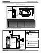
R Mt. Vernon Pellet Insert (AE) B. Component Locations Low Fuel Indicator Drop Tube Door Switch Control Board Convection Blower Exhaust Blower Auger Optical Switch behind Feed Motor Feed Motor Vacuum Switch Power Supply Figure 40.2 - Power Supply, Control Board, Convection Blower Re-set Button Heat Exchanger, Front & Back Overheat Sensor Baffle Wing Nut - Securing Overheat Sensor in place. Figure 40.
R Mt. Vernon Pellet Insert (AE) C. Exploded Views Item Description Part Number 1 Door Frame Assembly 7034-026 2 Latch Assembly, Door 7034-039 3 Glass Assembly 7034-007 4 Glass Retainer 7034-136 5 Hinge, Female 450-2910 6 Magnet & Bracket Assembly 7034-008 7 Door Air Deflector 7034-185 Glass Size: 21 in. w x 14 in. h. Figure 41.
R Mt. Vernon Pellet Insert (AE) Figure 42.
R Mt. Vernon Pellet Insert (AE) D. Service Parts and Accessories IMPORTANT: THIS IS DATED INFORMATION. The most current information is located on the Quadra-Fire web site at www.quadrafire.com. When ordering, supply serial number and model to ensure correct service parts. Item No. Accessories Part No.
R Mt. Vernon Pellet Insert (AE) Item No. 42 Service Parts Part No.
R Item No. Mt. Vernon Pellet Insert (AE) Service Parts Part No.
R Mt. Vernon Pellet Insert (AE) Item No. Service Parts Part No.
R Mt. Vernon Pellet Insert (AE) E.
R Mt. Vernon Pellet Insert (AE) E.
R Mt. Vernon Pellet Insert (AE) F.
R Mt. Vernon Pellet Insert (AE) G. Warranty Policy Hearth & Home Technologies LIMITED WARRANTY Hearth & Home Technologies (“HHT”) and its respective brands extends the following warranty for HHT gas, wood, pellet and electric appliances purchased from an authorized HHT dealer and installed in the United States of America or Canada. Warranty starts with date of purchase by the original owner (End User) except as noted for replacement parts.
R Mt.
R CONTACT INFORMATION: Hearth & Home Technologies 1445 North Highway Colville, WA 99114 Division of HNI INDUSTRIES Please contact your Quadra-Fire dealer with any questions or concerns. For the number of your nearest Quadra-Fire dealer visit our web site at www.quadrafire.com NOTICE • Leave this manual with party responsible for use and operation.