
user manual

4
Heat & Glo • 6000TRSI-AUC • 2078-900 Rev. G • 12/06
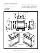
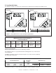
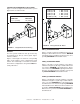
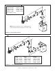
FIGURE 1.1 Diagram of the 6000 Series
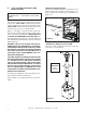
1.0 INSTALLATION INSTRUCTIONS
When planning a heater installation, it’s necessary
to determine:
• Where the unit is to be installed.
• The flue system configuration to be used.
• Gas supply piping.
• Electrical wiring.
• Framing and finishing details.
If the heater is to be installed on carpeting or tile, or on
any combustible material other than wood flooring, the
heater should be installed on a metal or wood panel
that extends the full width and depth of the heater.
2-1/2
64
[
]
5
126.9
[
]
27
686
[]
6-7/8
174
[]
2-3/8
61
[]
Ø
8
203[
]
9-7/8
250[
]
28-3/8 722[
]
14-1/4
362
[
]
21-1/2
547[]
18-3/4
476[
]
31-5/8
803[
]
41 1043[
]
36-1/8
917[
]
38
965[
]
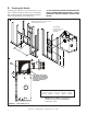
ELECTRICAL
ACCESS
GAS LINE
ACCESS
TOP
STANDOFFS
GLASS
DOOR
DATA BADGE & LABELS
ELECTRICAL
ACCESS
GAS CONTROLS
AND SWITCHES
GAS LINE
ACCESS
(BEHIND ACCESS DOOR)