Owner’s Manual Installation and Operation Model(s): EDV3633, EDV3633L, EDV3633I, EDV3633IL Direct Vent Gas Appliance CAUTION T O N RD O A D SC I D DO NOT DISCARD THIS MANUAL • Important operating and • Read, understand and follow • Leave this manual with party responsible for maintenance instructions these instructions for safe installation and operation. use and operation. included.
Read this manual before installing or operating this appliance. Please retain this owner’s manual for future reference. A. Congratulations Congratulations on selecting a Heatilator gas fireplace, an elegant and clean alternative to wood burning fireplaces. The Heatilator gas fireplace you have selected is designed to provide the utmost in safety, reliability, and efficiency. As the owner of a new fireplace, you’ll want to read and carefully follow all of the instructions contained in this owner’s manual.
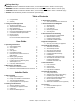
Safety Alert Key: • • • • DANGER! Indicates a hazardous situation which, if not avoided will result in death or serious injury. WARNING! Indicates a hazardous situation which, if not avoided could result in death or serious injury. CAUTION! Indicates a hazardous situation which, if not avoided, could result in minor or moderate injury. NOTICE: Used to address practices not related to personal injury. Table of Contents A. Congratulations B. Warranty 2 5 1 Listing and Code Approvals A. B. C. D. E. F. G.
14 Appliance Setup A. B. C. D. E. F. G. H. I. Remove Packaging Materials Remove Glass Assembly Logs Place Lava Rock, Rockwool Replace Glass Install Floor Cover Grilles and Screen Air Shutter Setting Accessories 46 46 46 46 47 47 47 48 48 15 Troubleshooting A. Standing Pilot Ignition System B. Intellifire Ignition System 49 51 16 Reference Materials A. B. C. D. E.
B. Warranty Hearth & Home Technologies LIMITED WARRANTY Hearth & Home Technologies (“HHT”) and its respective brands extends the following warranty for HHT gas, wood, pellet and electric appliances purchased from an authorized HHT dealer and installed in the United States of America or Canada. Warranty starts with date of purchase by the original owner (End User) except as noted for replacement parts.
B. Warranty (continued) This limited warranty does not extend to or include surface finish on the appliance or terminations, door gasketing, glass gasketing, glass discoloration, firebrick, pellet logs, kaowool or other ceramic insulating materials. Rust and/or corrosion on any of the metal surfaces, cast iron components, baffles, firepots, doors, or firebox area are not covered by this warranty.
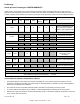
1 Listing and Code Approvals A. Appliance Certification C. BTU Specifications MODELS: EDV3633, EDV3633L, EDV3633I, EDV3633IL LABORATORY: Underwriters Laboratories, Inc. (UL) TYPE: Vented Gas Fireplace STANDARD: ANSI Z21.88-2005•CSA2.33-2005•UL307B This product is listed to ANSI standards for “Vented Gas Fireplace” and applicable sections of “Gas Burning Heating Appliances for Manufactured Homes and Recreational Vehicles”, and “Gas Fired Appliances for Use at High Altitudes”.
Note: The following requirements reference various Massachusetts and national codes not contained in this document. H.
2 User Guide Operating Instructions A. Gas Fireplace Safety • WARNING HOT SURFACES! Glass and other surfaces are hot during operation and cool down. Hot glass will cause burns. • Do not touch glass until it is cooled • NEVER allow children to touch glass • Keep children away • CAREFULLY SUPERVISE children in same room as appliance. • Alert children and adults to hazards of high temperatures. High temperatures may ignite clothing or other flammable materials.
C. Fan Kit G. Before Lighting Fireplace • • Before operating this fireplace for the first time, have a qualified service technician: Optional Contact your dealer for the correct fan kit. • D. Clear Space WARNING! DO NOT place combustible objects in front of the fireplace or block louvers. High temperatures may start a fire. See Figure 2.2. Avoid placing candles and other heat-sensitive objects on mantel or hearth. Heat may damage these objects.
Heatilator • Eclipse • 4049-229 Rev F • 11/08 D. C. Use only your hand to push in and move the gas control valve or turn the gas control knob. Never use tools. If the lever or knob will not move by hand, don't try to repair it, call a qualified service technician. Force or attempted repair may result in a fire or explosion. Do not use this appliance if any part has been under water.
7 5 OFF Heatilator • Eclipse • 4049-229 Rev F • 11/08 OFF 11 Due to high surface termperatures, keep children, clothing and furniture away. Keep burner and control compartment clean. See installation and operating instructions accompanying the appliance. 29097D Turn manual gas valve to "CLOSED position. Do not force. Replace control access panel. 8 ON 3. 4. 5 T Turn off wall switch or set thermostat to lowest setting. Remove control access panel. TO TURN OFF GAS TO APPLIANCE 4. OPEN 3.
J. After Fireplace is Lit Initial Break-in Procedure • The fireplace should be run three to four hours continuously on high. • Turn the fireplace off and allow it to completely cool. • Remove fixed glass assembly. See Section 14.B. • Clean fixed glass assembly. See Section 3. • Replace the fixed glass assembly and run continuously on high an additional 12 hours. This cures the materials used to manufacture the fireplace. NOTICE! Open windows for air circulation during fireplace break-in.
3 Maintenance and Service Any safety screen or guard removed for servicing must be replaced prior to operating the fireplace. • When properly maintained, your fireplace will give you many years of trouble-free service. We recommend annual service by a qualified service technician. A. Maintenance Tasks-Homeowner Installation and repair should be done by a qualified service technician only. The fireplace should be inspected before use and at least annually by a professional service person.
Venting Control Compartment and Firebox Top Frequency: Seasonally Frequency: Annually By: Homeowner By: Qualified Service Technician Tools needed: Protective gloves and safety glasses. • Inspect venting and termination cap for blockage or obstruction such plants, bird nests, leaves, snow, debris, etc. • Verify termination cap clearance to subsequent construction (building additions, decks, fences, or sheds). See Section 6. • Inspect for corrosion or separation.
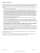
IC F CI T C U E P S D O R (Either cobrahead or SIT) P Figure 3.1 IPI Pilot Flame Patterns Figure 3.
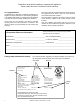
4 Getting Started Installer Guide A. Typical Appliance System NOTICE: Illustrations and photos reflect typical installations and are for design purposes only. Illustrations/diagrams are not drawn to scale.
B. Design and Installation Considerations D. Inspect Appliance and Components Heatilator direct vent gas appliances are designed to operate with all combustion air siphoned from outside of the building and all exhaust gases expelled to the outside. No additional outside air source is required. • Installation MUST comply with local, regional, state and national codes and regulations.
5 Framing and Clearances A. Selecting Appliance Location When selecting a location for the appliance it is important to consider the required clearances to walls (see Figure 5.1). NOTICE: Illustrations reflect typical installations and are FOR DESIGN PURPOSES ONLY. Illustrations/diagrams are not drawn to scale. Actual installation may vary due to individual design preference. WARNING! Risk of Fire or Burns! Provide adequate clearance around air openings and for service access.
B. Constructing the Appliance Chase A chase is a vertical box-like structure built to enclose the gas appliance and/or its vent system. In cooler climates the vent should enclosed inside the chase. NOTICE: Treatment of ceiling firestops and wall shield firestops and construction of the chase may vary with the type of building. These instructions are not substitutes for the requirements of local building codes. Therefore, you MUST check local building codes to determine the requirements to these steps.
D. Mantel and Wall Projections Mantel Legs or Wall Projections WARNING! Risk of Fire! Comply with all minimum clearances to combustibles as specified. Framing or finishing material closer than the minimums listed must be constructed entirely of noncombustible materials (i.e., steel studs, concrete board, etc). Mantels Top of Appliance Note: All measurements in inches. Drywall 30 in. minimum to ceiling 18 A 2 in. (51 mm) min.
6 Termination Locations A. Vent Termination Minimum Clearances Measure vertical clearances from this surface. WARNING Fire Risk. Maintain vent clearance to combustibles as specified. • DO NOT pack air space with insulation or other materials. Failure to keep insulation or other materials away from vent pipe may cause overheating and fire. Horizontal overhang Termination Cap Storm Collar Roof Flashing (See Figure 6.5 for specific clearances) Figure 6.2 Clearance To Horizontal Termination Cap 20 in.
H D O E N V L V C B Fixed Closed V F V B Openable Fixed Closed V V G V B B B V J X M V I A V TERMINATION CAP K X GAS METER X AIR SUPPLY INLET Measure vertical clearances from this surface Q RESTRICTION ZONE (TERMINATION NOT ALLOWED) V P W V R V T U U V V Covered Alcove Applications Dimension Descriptions Electrical Service D* S Measure horizontal clearances from this surface.
7 Vent Information and Diagrams A. Approved Pipe Vertical 12 in . DO NOT mix pipe, fittings or joining methods from different manufacturers. The pipe is tested to be run inside an enclosed wall. There is no requirement for inspection openings at each joint within the wall. 8-1/2 in. This appliance is approved for use with Hearth & Home Technologies SLP venting systems. Refer to Section 16B for vent component information. 8-1/2 in. WARNING! Risk of Fire or Asphyxiation.
E. Vent Diagrams To replace the first starter elbow with two 45° elbows, refer to Figure 7.4. All other 90° elbows can be replaced with two 45° elbows. General Rules: • • • • • • • SUBTRACT 3 ft. from the total H measurement for each 90° elbow installed horizontally. SUBTRACT 1-1/2 ft. from the total H measurement for each 45° elbow installed horizontally. A maximum of three 90° elbows (or six 45° elbows) may be used in any vent configuration. Some elbows may be installed horizontally. See Figure 7.9.
1. Top Vent - Horizontal Termination - (continued) Two 45° Elbows replacing One 90° Elbow 4 ft min. (1.22 m) 25 ft max. (7.62 m) Figure 7.4 Two Elbows Note: For corner installations: A 6 in. (152 mm) section of straight pipe may need to be attached to the appliance before a 90º elbow, to allow the vent pipe to clear the top standoffs. V1 min. V1 max. ft m H1+H2 max. H1+H2+H3 max. ft m ft 0.5 0.15 - - 6 1.83 - - 1 0.30 - - 11 3.35 11 3.35 1.5 0.46 - - 18 5.49 18 5.
1. Top Vent - Horizontal Termination - (continued) V1 min. Three Elbows V1 + V2 max. H1+H2 max. ft m ft m ft m 1 0.30 24 7.32 19 5.79 H2 V2 H1 V1 Figure 7.
2. Top Vent - Vertical Termination Note: If installing a vertical vent/ termination off the top of the appliance, the flue restrictor should be used. No Elbow 12 ft (3.66 m) min. 60 ft (18.29 m) min. Figure 7.7 Two Elbows Maximum horizontal run is 100% of vertical, but cannot exceed 26 ft (7.92 m) 12 ft (3.66 m) min. 60 ft (18.29 m) max. Figure 7.
2. Top Vent - Vertical Termination - (continued) Three Elbows Maximum horizontal run is 100% of vertical, but cannot exceed 26 ft (7.92 m) 12 ft (3.66 m) min. 60 ft (18.29 m) max. Figure 7.
8 Vent Clearances and Framing A. Pipe Clearances to Combustibles B. Wall Penetration Framing WARNING! Risk of Fire! Maintain air space clearance to vent. DO NOT pack insulation or other combustibles: Combustible Wall Penetration • Between ceiling firestops • Between wall shield firestops • Around vent system Failure to keep insulation or other material away from vent pipe may cause over heating and fire. Whenever a combustible wall is penetrated, you must frame a hole for the wall shield firestops.
C. Install the Ceiling Firestop A ceiling firestop MUST be used between floors and attics. • • • • Frame opening 9 in. x 9 in. (229 mm x 229 mm) whenever the vent penetrates a ceiling/floor (see Figure 8.3). Frame the area with the same sized lumber as used in ceiling/floor joist. The ceiling firestop may be installed above or below the ceiling joists when installed with a attic insulation shield. It must be under joists between floors that are not insulated. Refer to Figure 8.4.
D. Install Attic Insulation Shield WARNING! Fire Risk. DO NOT allow loose materials or insulation to touch vent. Hearth & Home Technologies Inc. requires the use of an attic shield. The National Fuel Gas Code ANSI Z223.1 and NFPA 54 requires an attic shield constructed of 26 gauge minimum metal that extends at least 2 in. (51 mm) above insulation. Attic shields must meet specified clearance and be secured in place. Flat Ceiling Installation • Remove one shield from box.
9 Appliance Preparation A. Securing and Leveling the Appliance WARNING! Risk of Fire! Prevent contact with: • • • Sagging or loose insulation Insulation backing or plastic Framing and other combustible materials Block openings into the chase to prevent entry of blown-in insulation. Make sure insulation and other materials are secured. DO NOT notch the framing around the appliance standoffs. Failure to maintain air space clearance may cause overheating and fire.
10 Installing SLP Vent Pipe A. Assemble Vent Sections B. Assemble Slip Sections To attach the first vent component to the starting collars of the appliance • Lock the vent components into place by sliding the pipe section onto the collar. Align the seam of the pipe and seam of collar to allow engagement. Rotate the vent component to lock into place. Use this procedure for all vent components. See Figure 10.1. Slide the gasket over the first vent section and place it flush to the appliance.
C. Securing the Vent Sections D. Disassemble Vent Sections • • • • • • Vertical runs of SLP pipe must be supported every 8 ft. (2.44 m). Horizontal sections of vent must be supported every 5 ft. (1.52 m) with a vent support or plumber’s strap. Wall shield firestops may be used to provide horizontal support. Vent support or plumber’s strap (spaced 120° apart) may be used for support. See Figures 10.4 and 10.5. SLP ceiling firestops have tabs that may be used to provide vertical support.
E. Installing Metal Roof Flashing Note: Skip this section if using the RF4-8. • See minimum vent heights for various pitched roofs (Figure 10.8) to determine the length of pipe to extend through the roof. • Slide the roof flashing over the pipe sections extending through the roof as shown in Figure 10.9. NOTICE: Failure to properly caulk the roof flashing could cause water entry. • • Caulk the gap between the roof flashing and the outside diameter of the pipe.
F. Install RF4-8 The RF4-8 may be used in place of the roof flashing and storm collar (Sections 10.E. and 10.H.) Pipe must be supported within 12 in. (305 mm) of the roofline using plumbers strapping or an SLP-FS when using the RF4-8 Flashing. Refer to Sect. 10.C. Securing Vent Sections. Secure with 4 screws no longer than 1/2 in./13 mm Figure 10.12 Apply Sealant SLP-FS Figure 10.
G. Installing Vertical Termination Cap • H. Assemble and Install Storm Collar Attach the vertical termination cap by sliding the inner collar of the cap into the inner flue of the pipe section while placing the outer collar of the cap over the outer flue of the pipe section. Secure the cap by driving three self-tapping screws (supplied) through the pilot holes in the outer collar of the cap into the outer flue of the pipe (see Figure 10.15). • CAUTION! Risk of Cuts, Abrasions or Flying Debris.
I. Install Heat Shields and Horizontal Termination Cap WARNING! Risk of Fire! To prevent overheating and fire, heat shields must extend through the entire wall thickness. • DO NOT remove the heat shields attached to the wall shield firestop and the horizontal termination cap (shown in Figure 10.26). • Heat shields must overlap 1-1/2 in. (38 mm) minimum. There are two sections of the heat shield. One section is factory-attached to the wall shield firestop. The other section is factory-attached to the cap.
Install Horizontal Termination Cap • WARNING! Risk of Fire! The telescoping flue section of the termination cap MUST be used when connecting vent. • 1-1/2 (38 mm) minimum overlap of flue telescoping section is required. Failure to maintain overlap may cause overheating and fire. • • Vent termination must not be recessed in the wall. Siding may be brought to the edge of the cap base. Flash and seal as appropriate for siding material at outside edges of cap.
11 Gas Information A. Fuel Conversion C. Gas Connection • • • Make sure the appliance is compatible with available gas types. Conversions must be made by a qualified service technician using Hearth & Home Technologies specified and approved parts. • • B. Gas Pressure • • • Optimum appliance performance requires proper input pressures. Gas line sizing requirements will be determined in ANSI Z221.3 National Fuel Gas Code in the USA and CAN/ CGA B149 in Canada.
12 Electrical Information B. Standing Pilot Ignition System Wiring A. Wiring Requirements NOTICE: This appliance must be electrically wired and grounded in accordance with local codes or, in the absence of local codes, with National Electric Code ANSI/NFPA 70-latest edition or the Canadian Electric Code CSA C22.1. Wire the appliance junction box to 110-120 VAC. This is required for use of optional accessories (standing pilot ignition) or proper operation of the appliance (Intellifire ignition).
E. Electrical Service and Repair WARNING! Risk of Shock! Replace damaged wire with type 105° C rated wire. Wire must have high temperature insulation. WARNING! Risk of Shock! Label all wires prior to disconnection when servicing controls. Wiring errors can cause improper and dangerous operation. Verify proper operation after servicing.
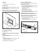
F. Junction Box Installation If the box is being wired from the OUTSIDE of the appliance: Romex Connector • Remove the cover plate located on the outer shell - right side (see Figure 12.4). • Install the supplied Romex™ connector in the cover plate. If the box is being wired from the INSIDE of the appliance: • Remove the screw attaching the junction box/receptacle to the outer shell, rotate the junction box inward to disengage it from the outer shell (see Figure 12.4).
13 Finishing A. Mantel and Wall Projections B. Facing Material WARNING! Risk of Fire! Comply with all minimum clearances to combustibles as specified. Framing or finishing material closer than the minimums listed must be constructed entirely of noncombustible materials (i.e., steel studs, concrete board, etc). • • • Mantels • • Note: All measurements in inches. 30 in.
14 Appliance Setup A. Remove Packaging Materials • Face parts are shipped in tube on glass protector. To remove glass protector unlatch top glass latches and remove glass protector. Pull the four glass assembly latches out of the groove on the glass frame. See Figure 14.3 Latches (both bottom and top) Glass Latches Glass Assembly Figure 14.3 Glass Assembly Face Parts Inside • • Remove the glass panel from the appliance. Lay aside on a nonabrasive surface. C. Logs Figure 14.
• Place a small amount of 1/2 in. (13 mm) diameter pieces (dime-size) of rockwool on the burner pan so that the rockwool touches but does not cover the holes in the burner pan. This will provide the “glowing embers” look. It is not necessary to use the entire bag. Save the remaining rockwool for future use. See Figure 14.6. G. Grilles and Screen • • • Lay top grille face down so the thin tabs are pointing up. Spread screen out next to the tab side of the grille.
• Swivel the top grill toward the unit and apply slight pressure downward and push forward until the notch locks into the slot. Refer to Figure 14.11. To remove grill, apply slight pressure downward (center of grill) and pull out. • Notch H. Air Shutter Setting This appliance has an adjustable air shutter (which controls the primary air) that can be accessed under the valve compartment located under the firebox assembly (Figure 14.13). The air shutter is factory set for the minimum vertical vent run.
15 Troubleshooting With proper installation, operation, and maintenance your gas appliance will provide years of trouble-free service. If you do experience a problem, this troubleshooting guide will assist a qualified service technician in the diagnosis of a problem and the corrective action to be taken. This troubleshooting guide can only be used by a qualified service technician. Contact your dealer to arrange a service call by a qualified service technician. A.
Troubleshooting (continued) Symptom 3. (Continued) Possible Cause Corrective Action C. Failed valve. Turn the valve knob to the ON position. Place the ON/OFF switch in the ON position. Check the millivolt meter a the thermopile terminals. The millivolt meter should read greater than 125mV. If the reading is acceptable, and if the burner does not come on, replace the gas valve. D. Plugged burner orifice. Check the burner orifice for stoppage. Remove stoppage. E. Wall switch or wires.
B. Intellifire Ignition System Symptom 1. Pilot won’t light. The ignitor/module makes noise, but no spark. Possible Cause A. Incorrect wiring. Corrective Action Verify “S” wire (white) for sensor and “I” wire (orange) for ignitor are connected to correct terminals on module and pilot assembly. B. Loose connections or electrical Verify no loose connections or electrical shorts in wiring from shorts in the wiring. module to pilot assembly.
Intellifire Ignition System - (continued) Symptom Possible Cause 4. Pilot lights but continues A. A shorted or loose connection to spark, and main burner in flame sensing rod. will not ignite. (If the pilot continues to spark after the pilot flame has been lit, flame rectification has not B. Poor flame rectification or occurred.) contaminated flame sensing rod. 52 Corrective Action Verify all connections to wiring diagram in manual. Verify connections underneath pilot assembly are tight.
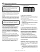
16 Reference Materials A. Appliance Dimension Diagram Dimensions are actual appliance dimensions. Use for reference only. For framing dimensions and clearances refer to Section 3. 17-1/8 in. 435 mm 10-7/8 in. 276 mm 33-1/4 in./845 mm 35-1/2 in./902 mm 5 in. 127 mm 33-1/2 in. 851 mm 28-1/2 in. 724 mm 6-1/2 in. 165 mm 3 in. 76 mm 20-5/8 in. 524 mm 2-3/16 in. 56 mm Alternative Gas Access 3/4 in. 19 mm 5-3/8 in. 137 mm 12-5/8 in. 321 mm Figure 16.
B. Vent Components Diagrams 6-1/2 in. 165 mm 6-1/2 in. 165 mm 8-3/4 in. 222 mm 6-1/2 in. 165 mm 9-1/4 in. 235 mm 6 in. 152 mm 6-5/8 in. 168 mm 6-5/8 in. 168 mm SLP-45 - 45° Elbow 9-7/8 in. 251 mm SLP-90ST - 90° Elbow Effective Height/Length Effective Height/ Length SLP-Pipe Pipe inches mm SLP4 4 102 SLP6 6 152 SLP12 12 305 SLP24 24 610 SLP36 36 914 SLP48 48 1219 SLP6A 2-6 51 - 152 SLP12A 2 - 12 51 - 305 SLP-HVS Horizontal Pipe Support RF4-8 Roof Flashing 26 in.
B. Vent Components Diagrams (continued) SLK-SNKD Snorkel Termination Cap SLP-TVHW Vertical Termination Cap DVP-FBHT Horizontal Termination Cap (This termination cap requires an SL-2DVP adapter when used with SLP Pipe) PVK-80 Power Vent SL-2DVP Adapter 13 in. (330 mm) 8-1/8 in. (206 mm) 15 in. (381 mm) SLP-TRAP1 Horizontal Termination Cap SLP-HRC-SS Effective Length 5-3/4 to 8-3/8 in. 146 to 213 mm 5-1/2 in. 140 mm 87° 8-3/8 in. 213 mm 3° 10-1/2 in. 267 mm 10-7/8 in.
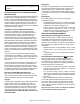
14 13 12 11 10 Service Parts 7 5 4 Heatilator • Eclipse • 4049-229 Rev F • 11/08 2 EDV3633 15 16 08/08 Beginning Manufacturing Date: April 2008 Ending Manufacturing Date: Active 1 3 Log Set Assembly 9 8 6 Service Parts Diagram Ecilpse DV Y Y Y NGK-11 LPK-11 Regulator NG Regulator LP Additional service part numbers on following page.
14 13 12 11 10 Service Parts 7 5 4 Heatilator • Eclipse • 4049-229 Rev F • 11/08 2 1 15 16 08/08 Beginning Manufacturing Date: April 2008 Ending Manufacturing Date: Active EDV3633I, EDV3633IL 3 Log Set Assembly 9 8 6 Service Parts Diagram Ecilpse DV Y Y Y NPK-DXF LPK-DXF Regulator NG Regulator LP Additional service part numbers on following page.
Service Parts 4 5 2 1 6 Heatilator • Eclipse • 4049-229 Rev F • 11/08 Y Y Y N Y 4021-428 4021-435 4021-426 4041-042 28602 Bulkhead Orifice NG, Threaded (.083) Orifice LP, Threaded (.
D.
E. Contact Information Please contact your Heatilator dealer with any questions or concerns. For the location of your nearest Heatilator dealer, please visit www.heatilator.com.