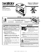
Owner’s Manual Installation and Operation Model(s): BCBV36 / BCBV36I B-Vent Gas Appliance NOTICE DO NOT DISCARD THIS MANUAL • Important operating and maintenance instructions included. • Read, understand and follow these instructions for safe installation and operation. • Leave this manual with party responsible for use and operation. WARNING WARNING: If the information in these instructions is not followed exactly, a fire or explosion may result causing property damage, personal injury, or death.
Read this manual before installing or operating this appliance. Please retain this owner’s manual for future reference. A. Congratulations Congratulations on selecting a Heatilator gas fireplace, an elegant and clean alternative to wood burning fireplaces. The Heatilator gas fireplace you have selected is designed to provide the utmost in safety, reliability, and efficiency. As the owner of a new fireplace, you’ll want to read and carefully follow all of the instructions contained in this owner’s manual.
Safety Alert Key: • • • • DANGER! Indicates a hazardous situation which, if not avoided will result in death or serious injury. WARNING! Indicates a hazardous situation which, if not avoided could result in death or serious injury. CAUTION! Indicates a hazardous situation which, if not avoided, could result in minor or moderate injury. NOTICE: Used to address practices not related to personal injury. Table of Contents A. Congratulations B. Warranty 2 4 1 Listing and Code Approvals A. B. C. D. E. F. G.
B.
B.
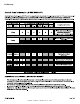
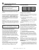
1 Listing and Code Approvals A. Appliance Certification C. BTU Specifications MODELS: BCBV36, BCBV36I BCBV36 Series Standing Pilot LABORATORY: Underwriters Laboratories, Inc. (UL) Input Rate (NG) TYPE: B-Vent Gas Appliance Heater Orifice Size (NG) STANDARD: ANSI 21.50b-2005/CSA 2.22b-2005 and Title This product is listed to ANSI standards for “Vented Gas Fireplaces” and “Gas Fired Appliances for Use at High Altitudes”.
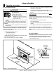
2 Operating Instructions User Guide A. Gas Fireplace Safety • WARNING HOT SURFACES! Glass and other surfaces are hot during operation AND cool down. Hot glass will cause burns. • DO NOT touch glass until it is cooled • NEVER allow children to touch glass • Keep children away • CAREFULLY SUPERVISE children in same room as fireplace. • Alert children and adults to hazards of high temperatures. High temperatures may ignite clothing or other flammable materials.
C. Clear Space F. Outside Air (optional) WARNING! DO NOT place combustible objects in front of the fireplace or block louvers. High temperatures may start a fire. See Figure 2.2. Avoid placing candles and other heat-sensitive objects on mantel or hearth. Heat may damage these objects. The outside air kit supplies some fresh combustion air for your fireplace. It may help reduce the effects of negative air pressure. (See Section 9.A.) • • Refer to Figure 2.1 for location of control.
H. Lighting Instructions (IPI) • • • For normal use, activate/deactivate your fireplace with the wall switch or remote control. The IPI system may be operated with two D-cell batteries. When using batteries, unplug the transformer. To prolong battery life, remove them when using the transformer. If your fireplace must be deactivated for serviced or an extended period of time, follow the instructions below. FOR YOUR SAFETY READ BEFORE LIGHTING WARNING: A. B.
Heatilator • BCBV36 • 4008-033 • Rev F • 12/08 7 8 OF F 11 Due to high surface termperatures, keep children, clothing and furniture away. Keep burner and control compartment clean. See installation and operating instructions accompanying the appliance. 29097D Turn manual gas valve to "CLOSED position. Do not force. Replace control access panel. 5 OFF 3. 4. 5 ON Turn off wall switch or set thermostat to lowest setting. Remove control access panel. TO TURN OFF GAS TO APPLIANCE 4. OPEN 3.
J. After Fireplace is Lit Initial Break-in Procedure • • • • • The fireplace should be run three to four hours continuously on high. Turn the fireplace off and allow it to completely cool. Clean glass doors. See Section 3. Run continuously on high an additional 12 hours. This cures the materials used to manufacture the fireplace. NOTICE! Open windows for air circulation during fireplace break-in. • • Some people may be sensitive to smoke and odors. Smoke detectors may activate. K.
3 Maintenance and Service Any safety screen or guard removed for servicing must be replaced prior to operating the fireplace. Doors, Surrounds, Fronts Frequency: Annually By: Homeowner When properly maintained, your fireplace will give you many years of trouble-free service. We recommend annual service by a qualified service technician. A. Maintenance Tasks-Homeowner Installation and repair should be done by a qualified service technician only.
Logs • Frequency: Annually By: Qualified Service Technician • Tools needed: Protective gloves. • Inspect for damaged or missing logs. Replace as necessary. Refer to Section 14.I. for log placement instructions. • Verify correct log placement and no flame impingement causing sooting. Correct as necessary. • • • Firebox Frequency: Annually • By: Qualified Service Technician Tools needed: Protective gloves, sandpaper, steel wool, cloths, mineral spirits, primer and touch-up paint.
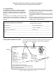
4 Installer Guide Getting Started A. Typical Appliance System NOTICE: Illustrations and photos reflect typical installations and are for design purposes only. Illustrations/diagrams are not drawn to scale.
B. Design and Installation Considerations D. Inspect Appliance and Components Heatilator B-type vent gas appliances are designed to operate with all exhaust gases expelled to the outside of the building, and combustion air pulled from the room. The following B-vent components are needed for installation. Installation MUST comply with local, regional, state and national codes and regulations.
E. Negative Pressure • WARNING! Asphyxiation Risk! Negative pressure can cause spillage of combustion fumes and soot. Fireplace needs to draft properly for safety. • • Draft is the pressure difference needed to vent fireplaces successfully. Considerations for successful draft include: • Preventing negative pressure • Location of fireplace and chimney Negative pressure results from the imbalance of air available for the fireplace to operate properly.
5 Framing and Clearances A. Select Appliance Location When selecting a location for the appliance it is important to consider the required clearances to walls (see Figure 5.1). NOTICE: Illustrations reflect typical installations and are FOR DESIGN PURPOSES ONLY. Illustrations/diagrams are not drawn to scale. Actual installation may vary due to individual design preference. WARNING! Risk of Fire or Burns! Provide adequate clearance around air openings and for service access.
C. Clearances NOTICE: Install appliance on hard metal or wood surfaces extending full width and depth. DO NOT install directly on carpeting, vinyl, tile or any combustible material other than wood. • WARNING! Risk of Fire! Maintain specified air space clearances to appliance and vent pipe: • Insulation and other materials must be secured to prevent accidental contact.
D. Mantel and Wall Projections WARNING! Risk of Fire! Comply with all minimum clearances as specified. Framing or finishing material closer than the minimums listed must be constructed entirely of noncombustible materials (i.e., steel studs, concrete board, etc). Mantels 35-1/2 in. minimum to ceiling 18 17 16 15 17-1/2 16-3/4 14 13 3 - 12 0-3 13 16 15-1/4 14-1/2 13-3/4 12-1/2 Measured from top of hood (in inches) Figure 5.
6 Termination Locations A. Vent Termination Minimum Clearances WARNING Fire Risk. Maintain vent clearance to combustibles as specified. • DO NOT pack air space with insulation or other materials. Failure to keep insulation or other materials away from vent pipe may cause overheating and fire. A B 6 in. (minimum) up to 20 in. 152 mm/508 mm 18 in. minimum 457 mm 20 in. and over 0 in. minimum Gas, Wood or Fuel Oil Termination Cap B A* 8 ft (2.
7 Vent Information and Diagrams A. Vent Guidelines WARNING! Fire Risk/Asphyxiation! This appliance requires the specified pipe for operation. Incorrect pipe may cause spillage, condensation and overheating. The BCBV36 models rquire 5 in. (127 mm) B-vent double wall vent pipe. • WARNING! Risk of Fire or Explosion! Insulation and other combustibles must not infringe on clearances. • • ALWAYS maintain specified clearances around venting and firestop systems. Install firestops as specified.
8 Vent Clearances and Framing A. Pipe Clearances to Combustibles Vent clearances are per vent manufacturer’s specifications. The vent MUST be Listed B-Vent pipe. WARNING! Risk of Fire! MAINTAIN AIR space clearance to vent. DO NOT pack insulation or other combustibles: • Between ceiling firestops • Between wall shield firestops • Around vent system Failure to keep insulation or other material away from vent pipe may cause over heating and fire. B.
9 Appliance Preparation A. Install Outside Air Kit Damper Assembly C. Secure and Level the Appliance CAUTION! Risk of Cuts/Abrasions/Flying Debris. Wear protective gloves and safety glasses during installation. Sheet metal edges are sharp. WARNING! Risk of Fire! Prevent contact with: WARNING! Risk of Fire/Asphyxiation. DO NOT draw outside combustion air from: • Wall, floor or ceiling cavity. • Enclosed space such as an attic or garage. • Close proximity to exhaust vents or chimneys.
10 Installing Vent Pipe A. Assembly of Vent Sections C. Secure Vent Sections This B-Vent appliance requires 5 in. B-vent double-wall pipe. Follow the pipe manufacturer’s installation guidelines when installing the unit. This will ensure proper operation and prevent safety hazards. Secure vent sections with vent supports following B-vent manufacturer’s instructions. WARNING! Risk of Fire/Exhaust Fumes! Assemble pipe sections per B-vent manufacturer’s instructions. Use support tabs for screws.
11 Gas Information A. Fuel Conversion C. Gas Connection • • • Make sure the appliance is compatible with available gas types. Conversions must be made by a qualified service technician using Hearth & Home Technologies specified and approved parts. • • B. Gas Pressure • • • Optimum appliance performance requires proper input pressures. Gas line sizing requirements will be determined in ANSI Z221.3 National Fuel Gas Code in the USA and CAN/ CGA B149 in Canada.
12 Electrical Information B. Standing Pilot Ignition System Wiring A. Wiring Requirements NOTICE: This appliance must be electrically wired and grounded in accordance with local codes or, in the absence of local codes, with National Electric Code ANSI/NFPA 70-latest edition or the Canadian Electric Code CSA C22.1. • Wire the appliance junction box to 110-120 VAC. This is required for use of optional accessories (standing pilot ignition) or proper operation of the appliance (Intellifire ignition).
E. Electrical Service and Repair WARNING! Risk of Shock! Replace damaged wire with type 105° C rated wire. Wire must have high temperature insulation. WARNING! Risk of Shock! Label all wires prior to disconnection when servicing controls. Wiring errors can cause improper and dangerous operation. Verify proper operation after servicing.
F. Junction Box Installation Your appliance is supplied with a Junction Box Kit. To operate the appliance with the supplied 3VAC transformer and/or remote control option, it is recommended that the junction box be installed and wired at this time to avoid reconstruction. • The Junction Box Kit is to be installed on the right side of the appliance; remove and discard the metal knockout. Attach the junction box bracket to the junction box as shown in Figures 12.4-12.6.
13 Finishing B. Facing Material A. Mantel and Wall Projections WARNING! Risk of Fire! Comply with all minimum clearances as specified. Framing closer than the minimums listed must be constructed entirely of noncombustible materials (i.e., steel studs, concrete board, etc.) Failure to comply could cause fire. Mantels • • • • • 35-1/2 in. minimum to ceiling 18 17 16 15 17-1/2 16-3/4 14 13 3 - 12 0-3 13 Metal front faces may be covered with non-combustible materials only.
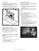
14 Appliance Setup A. Remove the Shipping Materials C. Clean the Appliance Remove shipping materials from inside or underneath the firebox. Clean/vacuum any sawdust that may have accumulated inside the firebox or underneath in the control cavity. B. Place the Control Access Panel • Remove the control access panel from its shipping location (Figure 14.1) by removing two screws holding it in place. Replace the two screws.
G. Place the Vermiculite I. Log Removal/Replacement • • • Sprinkle vermiculite evenly over the areas covered by lava rock. See Figure 14.4. • • • • Remove the lava rock from the appliance and save. Remove the top log which sits in the indents in the front log. Remove the two screws holding the front grate/log assembly in place (one per side from the hearth pan). See Figure 14.6. Pull forward on the assembly to remove it from the appliance and set aside. See Figure 14.7.
J. Hood The hood is located above the fireplace opening. The hood must be attached or a fire hazard may result. See Figure 14.9 to locate four screws holding the hood in place. Screws holding hood in place Figure 14.9 Hood Installation/Removal K. Air Shutter Setting The air shutter is provided in the closed position for natural gas and 1/8 in. open for propane. See Figure 14.10 for location of air shutter. • • • • Loosen the set screw. Rotate the air shutter to the right to open.
15 Troubleshooting With proper installation, operation, and maintenance your gas appliance will provide years of trouble-free service. If you do experience a problem, this troubleshooting guide will assist a qualified service technician in the diagnosis of a problem and the corrective action to be taken. This troubleshooting guide can only be used by a qualified service technician. Contact your dealer to arrange a service call by a qualified service technician. A.
A. Standing Pilot Ignition System (continued) 3. (continued) C. Valve. Turn the valve knob to the ON position. Place the ON/OFF switch in the ON position. Check the millivolt meter a the thermopile terminals. The millivolt meter should read greater than 125mV. If the reading is acceptable, and if the burner does not come on, replace the gas valve. D. Plugged burner orifice. Check the burner orifice for stoppage. Remove stoppage. E. Wall switch or wires.
B. Intellifire Ignition System Symptom 1. Pilot won’t light. The ignitor/module makes noise, but no spark. Possible Cause A. Incorrect wiring. Corrective Action Verify “S” wire (white) for sensor and “I” wire (orange) for ignitor are connected to correct terminals on module and pilot assembly. B. Loose connections or electrical Verify no loose connections or electrical shorts in wiring from module shorts in the wiring. to pilot assembly.
B. Intellifire Ignition System (continued) 4. Pilot lights but continues A. A shorted or loose connection to spark, and main burner in flame sensing rod. will not ignite. (If the pilot continues to spark after the pilot flame has been lit, flame rectification has not B. Poor flame rectification or occurred.) contaminated flame sensing rod. 5. The pilot and main burner extinguish while in operation. Verify all connections to wiring diagram in manual. Verify connections underneath pilot assembly are tight.
16 Reference Materials A. Appliance Dimension Diagram Dimensions are actual appliance dimensions. Use for reference only. For framing dimensions and clearances refer to Section 5. 21-3/4 in. (552 mm) 18-3/4 in. (476 mm) 11 in. (279 mm) 38-3/4 in. (984 mm) Outside Air 7-1/4 in. (184 mm) 11-7/8 in. (302 mm) 33 in. Electrical (838 mm) Access 27 in. (686 mm) 2-1/4 in. (57 mm) Gas Line Access 8-1/8 in. (206 mm) 2 in. (51 mm) 7 in. (178 mm) 7-1/4 in. (184 mm) 36 in. (914 mm) 2-1/2 in.
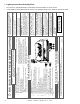
Heatilator • BCBV36 • 4008-033 • Rev F • 12/08 13 11 8 Part number list on following page. 14 12 10 9 7 6 5 4 1 BCBV36 2 3 15 16 09/08 Beginning Manufacturing Date: June 2003 Ending Manufacturing Date: Active Log Set Assembly Service Parts Diagram Builders Choice Service Parts Pre wk 14/04 Junction Box Heat Shield Junction Box Kit 16 Top & Bottom Face Additional service part numbers appear on following page. 71749 34891 31190 Qty.
6 Standing Pilot Valve Assembly 8 5 7 4 9 3 Service Parts Diagram Builders Choice Service Parts 2 1 10 SIT 11 12 RS 13 14 15 09/08 Beginning Manufacturing Date: June 2003 Ending Manufacturing Date: Active BCBV36 Log Retainer Brackets 4 Push Button Ignitor Flex Ball Valve Assembly Wire Assy HiBlk6FF 8 9 10 15 14 13 12 PART NUMBER 4008-014 Week 13/04 Thru Week 25/05 2103-010 Post GA1551065 Heatilator • BCBV36 • 4008-033 • Rev F • 12/08 Conversion Kit - NG to LP CKN SCKN-B
Heatilator • BCBV36 • 4008-033 • Rev F • 12/08 13 Part number list on following page.
Heatilator • BCBV36 • 4008-033 • Rev F • 12/08 8 7 5 4 10 9 2 3 1 14 12 13 11 15 16 20 09/08 17 Service Parts List Builders Choice Part number list on following page.
C. Optional Components ID4 Insulated Duct 4 in. (102 mm) i.d. 42 in. (1067 mm) UD4 Uninsulated Duct 4 in. (102 mm) i.d. 42 in. (1067 mm) AK22 - Air Kit .096 .110 Dexen Valve Burner Orifice .059 .093 .089 .115 DCKN Propane to Natural Gas Conversion Kit Pilot Orifice .110 .152 Pilot Orifice .056 .101 Burner Orifices .067 .182 Dexen Valve .
This page intentionally left blank.
D. Contact Information Please contact your Heatilator dealer with any questions or concerns. For the location of your nearest Heatilator dealer, please visit www.heatilator.com.