050 Fountain St. N. Cambridge, Ontario, Canada N3H 4R7 Bus. (519) 650-5501 Fax (519) 650-3773 Toll Free Phone 1-800-361-1517 Toll Free Fax 1-800-327-5609 INSTALLATION AND OPERATING INSTRUCTIONS Save these instructions for future use Model 7100 Note: Please read these instructions thoroughly before attempting to install this unit. WARNING: Improper installation, adjustment, alteration, service or maintenance can cause injury or property damage. Refer to this manual.
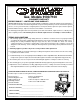
Gas Models 9100/7100 CONSUMER WARRANTY ENTIRE PRODUCT – LIMITED ONE YEAR WARRANTY HEARTLAND warrants the replacement or repair of all parts, including gas components of this Cookstove which prove to be defective in material or workmanship, with the exception of the painted or porcelain enamel finish or plated surfaces, for one year from the date of original purchase. Such parts will be repaired or replaced at the option of Heartland without charge, subject to the terms and conditions set out below.
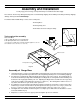
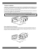
To move range for service or cleaning WARNING Range body rests on base. When moving, move by base only. 1. Disconnect electrical power. 2. Place temporary floor protection in front of range. 3. Slide out from wall and place floor protection under front legs and slowly pull out to gain access to rear. 4. To reinstall, reverse these instructions. The use of a gas cooking appliance results in the production of heat and moisture in the room in which it is installed.
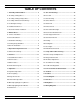
TABLE OF CONTENTS 1. Assembly and Installation .................................. 2 29. Care and Cleaning ............................................ 18 2. Assembly of Range Base ...................................... 2 30. Porcelain ............................................................. 18 3. Assembly of Range Body to Base ......................... 3 31. Oven Cleaning ..................................................... 19 4. Assembly of Exhaust Hood to Range .......................4 32.
Assembly and Installation To fully enjoy your new range, it is important that you read this booklet thoroughly. Note: Please check for any damage that may have occurred during shipping.
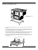
Assembly of Range Body to Base Lift the range at the front and rear, do not lift by nickel trim. 1. The range body rests directly on the base - no bolts are required. Two people are needed to lift it on to the base. 2. In order not to damage the nickel trim or enamel finish, lift the range from the front and the rear . The person at the front can first remove the oven door and use the oven opening for a hand hold. The rear of the oven body at the bottom can be used to lift from the back. 3.
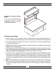
Assembly of Exhaust Hood to Range See the manual entitled "Cabinet Assembly Instructions for Gas , Electric ,Combination and Wood Stoves" which is included with the cabinet . Positioning the Range 1. When the range is fully assembled, recheck all electrical connections especially between the exhaust hood and the back of the range. As well, check that all nuts and bolts have been tightened. 2. Ensure teflon gliders and flooring are clean, (as described in the second paragraph under "Assembly of Range Base".
Installation Clearances If the range must stand beside a refrigerator, it is important for proper air circulation, that there be at least 5" of space between the two appliances. Do not install range closer than 1/2" from adjacent surfaces. To eliminate the risk of burns or fire by reaching over heated surface units, installation of cabinet storage space above the surface units should be avoided. If there is existing cabinet storage space have at least 30" of clearance.
Electrical Installation THE MODEL 7100/9100 GAS RANGE MUST BE ELECTRICALLY GROUNDED IN COMPLIANCE WITH LOCAL CODES AND IN THE ABSENCE OF LOCAL CODES, WITH THE NATIONAL ELECTRICAL CODE ANSI/NFPA 70 “LATEST EDITION” IN THE U.S. OR THE CANADIAN ELECTRICAL CODE, PART I, CSA STANDARD C22.1 IN CANADA or YOUR NATIONAL ELECTRICAL CODE Connect the female end of the power cord to the main power (male) receptacle at the rear of the stove.
Exhaust Hood Your range is equipped with a two speed range hood that may be either vented directly to the outside, or may be installed ventless. A set of exhaust filters are included with your hood. The filters should be cleaned periodically in soapy water. Extras are available from your dealer or directly from Heartland Appliances Inc. Please order 4 or more filters at one time to save freight and handling charges. Phone your dealer for pricing and ordering instructions.
Installation of Ducting Installation through an outside wall Remove air deflector (used for ventless operation only). Cut appropriate-sized hole through the wall directly behind the range hood outlet (see Figure 6 ,page 7), making sure no wall studs are cut. Push range into position. From outside of the house, measure distance from the siding to the range outlet. Cut duct pipe that length, plus 1" (25mm) for overlap into outlet. Attach vent hood to pipe.
Venting Safety Guidelines Installation must be done in accordance with all local and national codes. Use only materials which conform to local codes in effect. Be sure power is disconnected before doing any electrical work. All duct work must be metal. Do not use plastic duct. The range hood should never be exhausted into a wall cavity or an attic where an accumulation of grease could become a fire hazard.
Important Safety Instructions 1. PROPER INSTALLATION—BE SURE YOUR APPLIANCE IS PROPERLY INSTALLED AND GROUNDED BY A QUALIFIED TECHNICIAN. 2. NEVER use this appliance as a space heater to heat or warm the room. Doing so may result in Carbon Monoxide poisoning and in overheating of the oven. 3. Do not leave children alone. Children should not be left alone or unattended in area where appliance is in use. They should never be allowed to sit or stand on any part of the appliance. 4.
Features J A B D C F E I H Figure 7 Cooking Controls The cooking controls are located on the right hand side of the cooktop; these controls offer an infinite number of heat settings for ease and accuracy in cooking and baking. Sealed Burner Features (see fig. 7) A) Centre Burners - are two maximum 8,000 BTU (2.34 kW)(L/P 7,000 BTU) with simmer of 600 BTU (.2 kW) sealed gas burners,easy clean, for medium duty cooking tasks. B) Left Burners - front sealed burner is maximum 10,000 BTU (2.
G L K Fig. 8 Oven Features E) Oven Temperature Control - With infinite bake temperature and broil control. All units feature "auto gas shutoff", which means that if for any reason the flame goes out, gas to the oven burner shuts off! F) Gas Oven Features: -baking -3 position racking -2 cubic feet of energy efficient area (.05 cubic meters) -13,500 BTU (3.96Kw) oven burner Other Features (see fig. 8) G) Digital Clock - With minute minder.
Control Panel Layout Model 7100 Control Panel The control panel is laid out in a straight line and each control is identified by a graphic on the right side of the knob.
OPERATION Top Burner Operation Lighting the Top Burners Your range is equipped with a spark ignition system that is electrically operated. You need only to push in and turn the knob to any position and the burner will light. When you turn the knob, you will hear a distinct clicking noise. After the burner lights, the clicking noise will stop. Note: when lighting any one burner, all burners will spark, but only the burner that you have selected will light.
Oven Cooking Oven Lighting Open oven door. There are 2 holes in the oven bottom so you can view the oven flame. Push in and hold down the oven knob and select the desired oven temperature. You should hear sparking until the oven flame ignites. You must continue to keep oven knob depressed for 5-6 seconds after the oven ignition has occurred. The extra 5-6 seconds is to heat up the safety thermocouple to allow proper oven control.
Power Failure Operation If electrical power is interrupted in your area, you can still cook meals on your Heartland gas range .By following these simple directions you will be able to use the burners and oven without the benefit of electricity. Caution: make sure your hands and clothing are clear of the burner you are lighting! Top Burner Control Manually Lighting the Top Burners 1) Remove cast grate, for unobstructed access to the burner head. 2) Hold a flame source to the desired burner head.
Minute minder Adjust setting up Bell symbol indicates minute minder in operation Adjust setting down Clock / Timer NOTE: Clock must be set or your timer will not function! Functions: Reset minute minder Power on Press " Display is flashing " Set time of day Signal Press left button" " ". Set time of day with " " buttons. This function remains activated seconds after the last " "/" " and " " button together and release " button first.
Care and Cleaning CAUTION: When cleaning the cooking surface around the valve cover plate, be aware that detergents may corrode the electrical contacts on the valve switches (preventing an ignition spark) and may also degrade the gasket seal on the valve itself (causing a gas leak).
Oven Cleaning Your range must be kept clean and free of accumulations of grease or spillovers which may ignite. This is most important in the oven and broiling compartment. When cleaning the oven, make sure the oven is turned “Off” and oven is cool. For simple spills, clean the oven with a strong solution of detergent, then wipe with a clean damp cloth and dry. When food or grease has burned on the oven lining, apply a strong oven cleaning compound.
Nickel-Plated Trim Nickel may be cleaned with any non- abrasive chrome and metal polish or Windex and a soft cloth. If any acid-based food or liquid, such as lemon juice or tomato juice, is spilled on the range, wipe it at once to prevent staining. Exhaust Hood Exhaust filters are included with your exhaust hood. The filters may be cleaned periodically in soapy water. The filters should be replaced every 4 months or when they begin to restrict air flow.
Interior Oven Rack The oven rack is designed with stop-locks so that when placed correctly on the supports, it (a) will stop before coming completely out of the oven, (b) will not tip when placing or removing food. To install, place the rack "feet" on the rack support and push the oven rack backward along the rack support. (see 1 ) Push the oven rack all the way to the back until the oven rack slips off the end of the rack support.
Removal of Oven Door At times you may want to remove the oven door for thorough cleaning of the oven. Removal of the oven door is easy: 1) Open oven door, and latch the brass catches on to the upper leg of the hinge. (see below). Make sure the catch is securely hinged. 2) With a hand on each side of the door lift the door slightly, and pull out. 3) The door weighs about 17 lbs (8 kg) , so exercise caution when removing the door. 4) To replace the door reverse this sequence.
Broiling Broiling is cooking by direct radiated heat from above the food. It is fast because no preheat time is required and the food is close to the burner. When broiling, the oven control knob should be set to the broil symbol or the 550 setting on the knob. The oven door should be positioned at the first stop position on the door hinge, which will leave the door open approx. 5 inches.
Storage Drawer To remove storage drawer: 1. Remove oven door. 2. Remove oven bottom. 3. Pull drawer out until it stops. 4. With the aid of a flashlight, locate and remove the drawer stop at the left side of the drawer by removing the two screws. (see figure 1). 5. Pull the drawer again gently until it stops. At the same time, from underneath, pull on both release tabs (see figure 2) to disengage the drawer from the track and pull drawer out. 6.
SETUP AND TROUBLESHOOTING Timer Timer Exhaust Fan Speed Control Exhaust Fan Speed Control Filters Light Switch Filters Splashback Splashback Burner and Oven Controls Light Switch Burner and Oven Controls Oven Light Switch Oven Light Switch Oven Light Oven Light Broiler Drawer Broiler Drawer Pot Storage Burner Setup & Adjustment The range was carefully set up and inspected at the factory but some final adjustments may be necessary once the unit is installed.
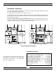
Air Shutter Adjustment (oven burner only) The quality of the flame can be changed by adjusting the air shutters. Factory setting on the air shutter is 0.40" (10.6mm). (see figure 9) loosen screw Reduce the shutter opening if: • the flame appears unsteady • is not burning all the way around • is noisy like a small blow torch. .4" 10.6 mm Increase the shutter opening if: • the flame has yellow tips • there is no sharp blue cone • soot appears on the bottom of cooking pans.
TROUBLESHOOTING GUIDE FOR ALL BURNERS EQUIPPED FOR REIGNITION WITH " FLAME RECTIFICATION " Problem Cause Remedy 1. No sparks when any control knob is turned to “light” No power to spark module - module switch faulty Check electrical supply to spark module with voltmeter - replace module 2.
Conversion Kits and Information Normally, Model 7100 and 9100 are ordered from the factory preset for either Natural Gas or Propane. However, they can be converted after installation by performing a conversion procedure to the gas components with the appropriate conversion kit. The components requiring conversion are, 1) the pressure regulator, 2) top burner controls, 3)oven burner control, 4) the top burners 5) oven burner Kits can be ordered from your dealer or directly from Heartland.
See our complete line of kitchen appliances: 3010- 30" Classic II Series Refrigerator, 18 cubic feet capacity, bottom-mount freezer drawer, and convienient top-mount fresh food compartment. Ice maker is available as an option. The Classic series also offers an optional Cowl. Energy efficiency rating 548 kwh/year. Also available in Metro 3220 and Legacy 3060 models. 3110- 36" Classic II Series Refrigerator, 22 cubic feet capacity, top-mount freezer, counter-depth design. Ice maker is standard.
7100/9100 PARTS CHART 15 9 6 1 54 51 1 57 5 1 61 0 1 58 8 15 99 15 46 15 92 16 071 15 70 15 56 13 25 652 2 6 67 7 923 7 6 53 6 1551 15 211 737 4 6 679 75 45 75 30 63 13 13 021 13 07 111 0 111 5 91 41 11 2 5 11 2 01 6 6 76 -#7 100 6 6 75 -#9 100 7162 914 7 7 528 6 19 8 6 197 845 2 820 0 13 20 13 11 13 25 13 30 60 29 40 12 24 55 6 20 2 1 6 6 01 5 20 8 75 91 820 2 8 204 75 90 8 449 35 56 8 45 5 75 77 73 76 9 1 06 91 0 51 111 5 1 59 9 1 54 6 4 57 5 1 59 2 1 5 96 4 5 451 4 60 71 4 57 0 1 5
Model 7100 / 9100 Gas Range Parts Chart TO ENSURE THE CORRECT COLOR MATCH WHEN ORDERING COLORED PANELS, BOTH THE COLOR AND SERIAL NUMBER MUST BE PROVIDED.
Model 7100 / 9100 1050 FOUNTAIN ST N. CAMBRIDGE, ONTARIO CANADA N3H 4R7 Serial No. HGS Natural Gas LP/Propane Medium 8000 BTU/HR 7000 BTU/HR Large 10000 BTU/HR 9000 BTU/HR Oven 13500 BTU/HR 13500 BTU/HR Manifold Pressure 4 IN. W.C. 10 IN. W.C. Power Requirements 120 Volt 3 amps. 60 Hz This appliance can be used with LP/Propane gas and Natural gas. The gas appliance regulator must be set for the gas with which the appliance is used. Surface adjacent to cook top-left (7100) ................................
Wiring Diagrams Technical Data 7100 - Voltage 120 v / 60 Hz - Load 3 amps (model 9100) - Load 3 amps (model 7100) NOTE: Service amperage should be calculated by a qualified electrician. The maximum propane/natural gas supply inlet must not exceed 14 inches of water column. The minimum gas supply inlet should be at least 5 inches of water column for natural gas or at least 11 inches of water column for LP gas. NOTE: Gas services should be checked by a qualified gas technician.