
Gas Fireplace Owner's Installation and Operation Manual

Heat & Glo • 6000GLX-IPI-S/-R, 6000GLX-IPILP-S/-R • 2101-900 Rev. S • 12/0854
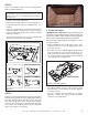
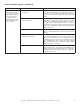
G. Install the Log Assembly
Log Assembly: LOGS-6000GLX
LOGS-6000GLXLP
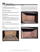
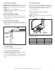
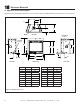
STEP 2. Place the metal grate on top of the
burner. Position the legs of the grate into the for-
ward set of indentations in the burner top, sliding
the grate forward. See Figure 14.8.
STEP 1. CAUTION: Logs are fragile! Carefully
remove the logs, grate and supporting cardboard
from the inside of the fireplace See Figure
14.7.
If the gas logs have been factory installed they
should not need to be positioned. If the logs have
been packaged separately, refer to the following
instructions.
Figure 14.8
Figure 14.8
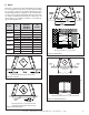
Figure 14.10 Top View
Figure 14.10 Top View
2101-910
1
1
2
2
3
3
4
4
5
5
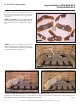
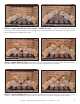
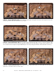
STEP 3. Log #1 NG (SRV2101-085): Log #1 LP (SRV2101-087): Log #1 is the left burning log. The air shut-
ter in the end of the burner tube goes over the left brass orifi ce located behind the main burner. The left end of the log goes
tight against the left refractory wall. See Figures 14.9 and 14.10.
1
1
Figure 14.7
Figure 14.7
1
1
Figure 14.9 Front View
Figure 14.9 Front View
6
6
7
7
HUMP
HUMP