
User's Manual


HC-08 BLUETOOTH UART COMMUNICATION MODULE USER MANUAL
WEB:www.hc01.com
PAGE
2
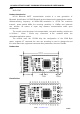
The HC-08 module has 30 pins, on board PCB antenna, pin specific definitions are listed in the
following table:
pin definition I/O explain
1 TXD output UART output, 3.3V TTL level
2 RXD input, weak pull up UART input, 3.3V TTL level
3 NC
4 NC
5 NC
6 DC input Debug clock
7 DD Input/output Debug data
8 P2.0 input, weak pull up NC
9 P1.7 input, weak pull down NC
10 P1.6 Input, weak pull down NC
11 nRST input, pull up Module reset pin, a low level of not less than 10ms reset
12 VCC input Power pin, the requirements of 3.3V DC power supply,
the supply current is not less than 100mA
13 GND Ground
14 LEDCON input LED control pin(Note④)
15 P1.4 input, weak pull down NC
16 P1.3 output LED output(Note①)
17 P1.1 output Link indicating(Note②)
18 P1.2 input, weak pull down The master module clear memory(Note③)
19 P1.0 input, weak pull down NC
20 P0.7 input, weak pull up NC
21 USB_D- NC
22 USB_D+ NC
23 P0.6 input, weak pull up NC
24 P0.1 input, weak pull up NC
25 P0.5 input, weak pull down NC
26 P0.0 input, weak pull up
27 VCC input Power pin, the requirements of 3.3V DC power supply,
the supply current is not less than 100mA
28 GND Ground
29 RXD input, weak pull up UART input, 3.3V TTL level
30 TXD output UART output, 3.3V TTL level