
Owners manual

Special Conditions
For tow vehicles equipped with factory trailer towing package:
• Refer to your vehicle-owner’s manual or other information provided by the manufacturer in
determining the correct connection points for the controller.
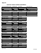
• See Appendix section for partial list of manufacturer wiring harness to controller conversions.
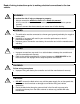
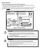
For vehicles without a trailer towing package refer to the wiring diagram in Figure 4.
(-)
NEGATIVE
POSITIVE
(+)
VEHICLE MECHANICAL
STOP LIGHT SWITCH
NON-POWERED STOPLIGHT WIRE
20A
20 AMP INLINE FUSE
20A
CHASSIS/GROUND
RED
BLACK
WHITE
BLUE
SELF-RESETING
20 AMP CIRCUIT
BREAKER
STOP LAMPS
12 VOLT
BATTERY
TOW VEHICLE/TRAILER
ELECTRICAL CONNECTOR
TRAILER BRAKES
TRAILER GROUND
GROUND
(NOT FURNISHED)
(NOT FURNISHED)
Figure 4 – Wiring Diagram
WARNING:
All 1999 and later Ford vehicles without the trailer wiring package:
• The red controller wire must be connected to the light green wire of the brake
stop lamp through a 20-amp inline fuse.
• Failure to install a 20-amp inline fuse can destroy the controller and void the
manufacturing warranty.
!
WARNING:
1989-1991 Ford Bronco, Econoline, F-Superduty, and F150-350 Series:
• The red stoplight wire MUST splice into the turn signal connector harness and
NOT to the stoplight switch.
• Connecting to the terminal of the stoplight switch will break the switch’s terminal
and result in no stoplights and no trailer braking.
!