
Owners manual
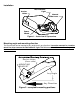
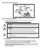
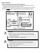

Controller Wiring
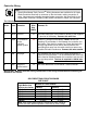
The following chart describes the function of each of the controller’s wires:
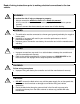
IMPORTANT: Make all controller wiring connections to the wiring harness before connecting the
harness to the vehicle.
Order Color Function Wire
Size
(AWG)
Connect To
1
st
White Ground 16 grounded metal part of the firewall or directly to the negative
(-) terminal of the battery. Connect this wire first.
2
nd
Black + Connection
to the
vehicle’s
power system
12
positive (+) terminal of the battery. MUST have a self-
resetting Circuit Breaker in-line between the controller and
the battery. See chart for proper size. Route the black wire
through a grommet hole in the fire wall to prevent wire
grounding and away from the radio antenna to reduce any
possible AM radio interference. Connect this wire second.
3
rd
Red Stoplight 14 non-powered stop lamp wire (of the stop lamp switch) or
trailer tow wiring harness. It is recommended that a 20-amp
inline fuse be installed between the controller’s red wire and
the stop lamp switch. The fuse is required in 1999 & later
Fords.
4
th
Blue Output to
trailer brakes
14 the trailer brake wire or tow vehicle / trailer connector.
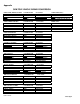
SELF-RESETTING CIRCUIT BREAKER
SIZE CHART
Number of Trailer Brakes
Number of Brake
Light Bulbs (tow
vehicle plus trailer)
2 Brakes 4 Brakes
4 Bulbs (minimum) 20 AMP 30 AMP
5 Bulbs
20 AMP 30 AMP
6 Bulbs
20 AMP 30 AMP
7 Bulbs
30 AMP 30 AMP
8 Bulbs
30 AMP 30 AMP
9 Bulbs
30 AMP 40 AMP
Note: Each trailer brake magnet is assumed to draw 3 amps of
current and each brake lamp bulb is assumed to draw 2 amps.
TIP:
• Special Dual-Mated “Quik Connect
TM
” Wiring Harnesses are available for all Hayes
Brake Controllers fitted with a connector on the wire leads, making connection a
snap. Harnesses are available through all dealer resources. Ask specifically for the
Ha
y
es Brake Controller Compan
y
(
HBC
)
brand harnesses to match
y
our controller.