ADSL Ethernet Modem U S E R ’ S G U I D E
NOTICE This document contains proprietary information protected by copyright, and this Manual and all the accompanying hardware, software, and documentation are copyrighted. No part of this document may be photocopied or reproduced by mechanical, electronic, or other means in any form.
Contents 1. INSTALLATION INSTRUCTIONS ........................................... 1 1.1 IMPORTANT! BEFORE YOU BEGIN ..................................... 1 1.2 PACKAGE CONTENTS ...................................................... 1 1.3 QUICK START INSTRUCTIONS ............................................... 3 Step 1: Installing the Software ......................................... 3 Step 2: Installing the Hardware ........................................ 4 Step 3: Configuring Internet Explorer...........
3.13 3.14 CONNECTION LOOPBACK ................................................59 NTP SERVER ..............................................................60 4. STATUS MONITORING .................................................... 61 4.1 ADSL STATUS ............................................................61 4.2 SYSTEM STATUS ..........................................................64 4.3 PROCESSES ................................................................66 4.4 MEMORY USAGE ....................
1 Installation Instructions 1.1 Important! Before You Begin Before you install your ADSL modem, you must have DSL service enabled on your telephone line. To do this, you need to sign up with a DSL service provider. 1.
The CD contains the installation software, documentation, warranty, and Customer Support information. If anything is missing or damaged, contact Hayes Customer Support or your retailer or distributor. In addition, you may have • DSL line filters (certain units only) • Phone-jack adapter to adapt the RJ-11 phone cord to a different phone jack (certain units only) You Will Also Need • A Windows 98SE/2000/Me/XP computer equipped with a Network Interface Card (NIC).
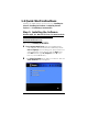
1.3 Quick Start Instructions Installing the ADSL Ethernet involves four steps: Installing the Software, Installing the Hardware, Configuring Internet Explorer, and Establishing Communication. Step 1: Installing the Software Windows 98SE, Me, 2000, and XP Users: You must install the software BEFORE connecting the hardware. Macintosh and Linux Users: You do not need to run the CD software. Skip to Step 2, Installing the Hardware. 1 Your computer must be on. Insert the supplied CD into your computer.
3 Click the ADSL Modem Installation Wizard button. 4 At the next screen, select ADSL Ethernet. The software installation then proceeds automatically. 5 When the process is complete, you will be prompted to click Finish. Now shut down your computer and install the modem hardware. Step 2: Installing the Hardware Your computer should be shut down.
The PWR light should become steady on, and the LINK light should blink once. If the PWR light doesn’t turn on, make sure there is power at the wall outlet or power strip where you plugged in the power cube. 3 Turn the computer on. 4 Plug one end of the supplied phone cord into the modem’s ADSL jack and the other end into the ADSL wall jack. The LINK light should blink and then become steady on. If it doesn’t, consult Appendix E, Troubleshooting.
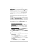
to Step 4, Establishing Communication, on page 7. Windows users: Your software that you use to make an Internet connection must be set for a network connection, not a dial-up connection. The instructions below are for Internet Explorer, the most popular Web browser. If you are using Netscape Navigator or another browser, set it up now to use a network connection (this might be called a “Local Area Network” or “broadband” connection). If you use Internet Explorer, you need Version 5 or later.
connection manually,” and then click Next. In the Internet Connection dialog box, click “Connect using a broadband connection that is always on,” and click Next. Windows 98/Me/2000 users: In the Internet Connection Wizard dialog box, select “I want to set up my Internet connection manually, or I want to connect through a local area network (LAN),” and click Next. In the Setting up your Internet connection dialog box, change the selection to “I connect through a local area network (LAN)” and click Next.
Click the icon to display the Hayes ADSL login page. If you do not have an icon on your desktop like the one shown above, open your Web browser, type http://10.0.0.2, and press Enter (or Return) to display the login page. If the login page doesn’t display, perform the following in this order: Recheck all connections; restart the modem and computer; and reset the modem by inserting a paper clip into the Reset pinhole and holding for five seconds.
4 The Basic Setup page displays. You need to fill in at least four of these boxes: Protocol, VPI, VCI, and Encapsulation. If your service provider gave you these settings, it will make installation a little faster and easier, but don’t worry if you don’t have them. We’ll tell you how to figure them out. If Your Service Provider Gave You Protocol, VPI, VCI, and Encapsulation Settings 1 If you have this information (Protocol, VPI, VCI, and Encapsulation), select the correct Protocol from the list.
NOT the User ID and Password that you used to get into the Basic Setup menu.) If you cannot remember or cannot find your User ID and Password, call your service provider and say that you have misplaced your user name and password. Then enter them as well. This information is required only with PPPoE and PPPoA protocols. 5 If you selected 1483 Bridged with Static IP or 1483 Routed with Static IP as your Protocol, your provider should have given you two series of numbers for the IP Address and Gateway.
For most users, the modem should take five minutes or less to test its settings for a possible match with your provider’s settings. 1 If your provider has given you a User ID and Password, select AutoPPP (the Basic Setup default). Otherwise, select AutoBridge and go to Step 2 on page 12. a When you select AutoPPP from the Protocol list, this page appears: b Make the following entries: c User ID Supplied by your service provider.
d As the modem searches for a match, click the ADSL Status button at the top of the page to go to the ADSL Status page. Under Connections Status, the State field indicates the search progress: e When the State field displays Connected, click the Advanced Setup button at the top of the page. (If the modem fails to find a match using the AutoPPP option, see Step 2 below.) f On the Advanced Setup page, click the Save Configuration button to save your provider’s Internet settings to permanent memory.
b The following field appears: Virtual Circuit c Accept the default, which is 0. Click Update and repeat Steps 1b – 1d above. When the modem connects, you are ready to explore the Internet. If and when you want to use your modem for online gaming, continue on page 16. If neither AutoPPP nor AutoBridge turns up a match for your provider’s settings, follow the instructions below.
3 Now enter the corresponding VPI, VCI, and Encapsulation settings in the appropriate boxes. 4 If you selected PPPoE as your protocol, leave the Service Name box empty. 5 If you selected either PPPoE or PPPoA as your Protocol, your provider should have given you a User ID or User Name (usually your email address or the characters preceding the @ sign in your email address) and a Password. (These are NOT the User ID and Password that you used to get into the Basic Setup menu.
If you do not connect successfully, continue with Step 10 below. 10 Go back to the table on page 74 and enter the next most frequently used settings – those labeled (2) if you just entered (1), or (3) if you just entered (2) – on the modem’s Basic Setup page, and repeat Steps 2 – 9 above. 11 If there are no more settings shown for your Service Provider, access the User’s Guide on the CD and consult Appendix E, Troubleshooting.
2 Online Gaming 2.1 Do I Need To Do Anything? There are three cases where you need to set up your modem in order to play online games. If you are using your computer to play a “peer-to-peer” or “head-to-head” game over the Internet, you always have to set up the modem unless you linked up to your partner by going to a web site. A peer-to-peer game is a game where two players are competing directly against one another.
2.2 Choosing an IP Address for Gaming You need to make sure that the computer or gaming system you use for playing games always has the same IP address. By default, the ADSL Ethernet assigns addresses dynamically (using Dynamic Host Configuration Protocol or DHCP) to the devices on the local area network whenever they reboot, and the addresses won’t necessarily always be the same. However, the modem can be set up to assign the same address to your computer or gaming system every time.
4 Before you can choose an IP address, you need to know the MAC (Media Access Control) address of your computer or gaming system. If you are using a computer to play an online game: If you know the name of your computer or if you have only one computer connected, you can find the MAC address under DHCP Clients (Leases) at the bottom of the DNS & DHCP Server page.
If you are using Xbox to play an online game: a You can find the MAC address on the Xbox Dashboard in the lower right corner of the Network Settings menu. You will see something like MAC=0050F24ADC29, but your address will be different. b You will also need to assign an IP address now. To do this, on the Xbox Network Settings menu select IP Addresses. c On the IP Addresses screen, enter the following: Configuration Manual IP Address 10.0.0.25 Subnet Mask 255.255.255.0 Gateway 10.0.0.
d On the Connection Test menu, select Advanced. The MAC address is displayed on the Advanced Broadband Settings screen. e Now, to configure the Playstation 2’s network settings, on the main menu select ISP Setup again. If a message displays, press X to disconnect from the Internet. f On the Edit Network Setting menu, select New Network Setting. g On the Connect to the Internet menu, select Local Area Network. h On the Local Area Network Setup menu, select Automatic Configuration.
system will always be assigned this address. 6 Next, use this IP address to set up a filter (open ports) in the ADSL Ethernet’s firewall. If you are using Xbox Live, go to page 23. If you have PlayStation 2, go to page 25. If you are playing a peer-to-peer or multiplayer game on your computer, follow the instructions below. 2.
NAT (Network Address Translation) Select this check box. Enable Select the first check box. Use Address Passthrough Do not select this check box. LAN IP Address Enter the IP address that you specified on the DNS & DHCP Server page. WAN IP Address If you only want to let certain people have access to your computer, you can do this by entering their computers’ WAN IP (Internet) addresses here.
Ports If you selected a game from the Protocol list or designated your computer as a DMZ, you do not have to enter anything here. If you are playing another peer-to-peer or multiplayer game, your game instructions should tell you what ports to enter here. To enter a number, you must enter tcp or udp in the Protocol box. You can specify a single port number (for example, 2400), a range of port numbers like 2400:2500 (which would be 2400, 2401, 2402, etc.
3 Make the following entries: Index An index number 1-7 to identify this filter configuration. In the sample, number 1 is selected. NAT Select this check box. Enable Select the first check box. Use Address Passthrough Do not select. LAN IP Address Enter 10.0.0.25. WAN IP Address Not required. Protocol Select the protocol specified in your Xbox instructions, either tcp or udp. Ports Type the port number(s) specified in the Xbox instructions. 4 Click Update and then Save Configuration.
8 Now you need to assign the filter to your Internet connection. Follow the instructions on page 26. 2.5 Setting Up a Firewall Filter for PlayStation® 2 1 Click the Advanced Setup button at the top of the ADSL Ethernet’s Configuration Manager page. 2 On the Advanced Setup page, click WAN IP Filter to display the WAN IP Filter page (the top of the page with a sample filter rule is shown below): Index An index number 1-7 to identify this filter configuration. NAT Select this check box.
4 Now you need to assign the filter to your Internet connection. Follow the instructions below. 2.6 Assigning the Filter to Your Internet Connection Note: If you have third-party firewall software, such as the Windows XP firewall, installed on your computer, you may need to deactivate it before setting up a filter. Otherwise your computer may block the ports you want to open. The final step in setting up the ADSL Ethernet is to open up ports for gaming by assigning the filter.
5 You will need to provide your WAN IP address to the people that you are playing with. To find this address, click the ADSL Status button at the top of your Configuration Manager page, scroll down to the Connections Status section, and note the address under IP Address, as shown below: That should complete your setup. Enjoy your game! Remember, to turn the modem’s firewall security back on, turn your filter off when you’ve finished. See below. 2.
Turning the Filter or DMZ On (Opening Ports for Gaming 1 Click the Advanced Setup button at the top of your Configuration Manager’s Basic Setup page. 2 On the Advanced Setup page, click the WAN Settings button. 3 On the WAN Settings page, in the WAN IP Filter box, select the number of your gaming filter (the number 1-7 that you chose earlier), click Update and then Save Configuration.
3 Advanced Setup Options In addition to its basic setup options, the ADSL Ethernet includes advanced settings for users who need to perform specialized tasks. To access the Advanced Setup options, click the Advanced Setup button at the top of your Configuration Manager’s Basic Setup page. IMPORTANT: Every time you make changes on an Advanced Setup page, click Update, then Save Configuration. If you don’t follow this procedure, any changes you’ve made will be lost when the ADSL Ethernet is reset.
3.1 WAN Settings Select WAN Settings to configure additional settings for the protocol you selected on the Basic Setup page of your Configuration Manager. There is a WAN Settings page for each of the Internet protocols on the Protocol list. The protocol and settings that appear when you click WAN Settings depend on the protocol you selected in Basic Setup. If you selected PPPoE or PPPoA, go to Section 3.1.1, PPP Connections, on page 31. If you selected 1483 Bridged w/DHCP, go to Section 3.1.
3.1.1 PPP Connections The following fields appear if you selected PPPoE or PPPoA on the Basic Setup page of your Configuration Manager: Make the following entries: Enable Lets you enable or disable the connection. VPI Supplied by your service provider. VCI Supplied by your service provider. Encapsulation LLC or VC. Supplied by your service provider. “Encapsulation” refers to the way information is packaged and sent over a network.
IP Address Passthrough Host MAC MAC address of the passthrough computer. The digit pairs must be separated by colons – for example, 00:01:03:24:F0:B6. For instructions on locating a MAC address, see Appendix C on page 77. User ID Supplied by your service provider. Password Supplied by your service provider. Service Name Supplied by your service provider. (Not required for PPPoA connections.) Authentication The method of verifying a user name and password.
Default Route Selected is the default for Virtual Circuit 0. The Default Route controls which connection will be used for default IP gateway routing. Only one Virtual Circuit can have this option selected. RIP Mode (Routing Information Protocol Mode). RIP allows you to share routing information with other routing devices on the WAN. Most small home or office networks do not need RIP, since they have only one router (the ADSL Ethernet) and one path to the ISP.
3.1.2 1483 Bridged with DHCP If you selected this protocol on the Basic Setup page of your Configuration Manager, the following fields appear: Make these entries: Enable Lets you enable or disable the connection. VPI Supplied by your service provider. VCI Supplied by your service provider. Encapsulation LLC or VC. Supplied by your service provider. See page 31. MAC Address The modem’s MAC address (display only).
Virtual Circuit Accept the default, which is 0, or if you are configuring an additional connection, select another number. See page 33. When you finish, click Update, then Save Configuration. 3.1.3 1483 Bridged with Static IP If you selected this protocol on the Basic Setup page of your Configuration Manager, these fields appear: Make the following entries: Enable Lets you enable or disable the connection. VPI Supplied by your service provider. VCI Supplied by your service provider.
Traffic Profile The index number 0-7 of a previously configured profile defining the Quality of Service. See page 54. WAN IP Filter The index number 0-7 of a previouslyconfigured WAN IP Filter. See page 42. Default Route Selected is the default for Virtual Circuit 0. See page 33. RIP Mode (Routing Information Protocol Mode). See page 33. Virtual Circuit Accept the default, which is 0, or if you are configuring an additional connection, select another number. See page 33. 3.1.
VCI Supplied by your service provider. Encapsulation LLC or VC. Supplied by your service provider. See page 31. IP Address The modem’s static IP address specified by your service provider. Gateway The gateway’s WAN IP address specified by your service provider. MTU (Maximum Transmission Unit) Value (in bytes) of the largest packet to be sent. Typically set to 1500. Traffic Profile The index number 0-7 of a previously configured profile defining the Quality of Service. See page 54.
3.1.5 1483 Bridged (Pure Bridge Mode) Note: Setting up the modem in Pure Bridged Mode disables the built-in NAT and SPI firewalls. If you selected this mode on the Basic Setup page of your Configuration Manager, the following fields appear: Make these entries: Enable Lets you enable or disable the connection. VPI Supplied by your service provider. VCI Supplied by your service provider. Encapsulation LLC or VC. Supplied by your service provider. See page 31.
3.1.6 AutoPPP If you selected AutoPPP in the Basic Setup pages, the following fields appear: Note that this page does not display the protocol, VPI, VCI, or encapsulation information for your connection. On the ADSL Status page, under Connections Status at the bottom of the page, you can determine the protocol, VPI and VCI. To find out the encapsulation, look for a line similar to “Found 0/38 PPPoA LLC” in the System Log file.
Passthrough Host MAC –for example, 00:01:03:24:F0:B6. For instructions on locating a MAC address, see page 77. User ID The name you entered and saved on the Basic Setup page is displayed. Password The password you entered and saved on the Basic Setup page is displayed. Inactivity Disconnect Timer The period of inactivity on the line after which the connection will be terminated – never (the default), 1 minute, 5 minutes, 20 minutes, or 1 hour.
b As the modem searches for a match, go to the ADSL Status page. Under Connections Status, the State field indicates the search progress. c When the State field displays Connected, click the Advanced Setup button . d On the Advanced Setup page, click the Save Configuration button to save your provider’s Internet settings and your configuration edits to permanent memory. Every time the modem reboots, it reconnects to the Internet automatically, using the new settings.
Traffic Profile The index number 0-7 of a previously configured profile defining the Quality of Service. See page 54. WAN IP Filter The index number 0-7 of a previouslyconfigured WAN IP filter. See page 42. Default Route Selected is the default. The Default Route controls which connection will be used for default IP gateway routing. Only one connection can have this option selected. RIP Mode (Routing Information Protocol Mode). See page 33. Virtual Circuit An index number 0-7.
room but allows water and electricity to travel through wellinsulated pipes in the wall to reach all parts of a building. Similarly, a computer firewall prevents unauthorized communication from gaining entry to your computer. You can open certain safe communication ports—to allow email communication, for example—but keep other ports sealed off from the outside world.
Game-players frequently designate one computer on their LAN as a DMZ (Demilitarized Zone), and allow all internet traffic to pass through the firewall to that computer. To set up a filter for online gaming or to create a DMZ, see Chapter 2, Online Gaming on page 16. Make these entries on the WAN IP Filter page of your Configuration Manager: Index A number 1-7 that will identify this filter configuration.
If you select udp or tcp, you must specify port numbers in the Ports field. If you select an application, the modem automatically enters the port number(s) into the rule. If you set up a rule to use all, make sure it is the last rule in the filter list. The ADSL Ethernet processes the rules from the top down, and when it sees all, it allows all packets through. If NAT is enabled and you select all, every packet that doesn’t match earlier rules in the filter list is forwarded to the specified LAN IP address.
3.3 LAN Interface The LAN Interface page of your Configuration Manager lets you configure the Host (modem) Name, IP Address, and Netmask, the Media (LAN connection transmission speed), and the RIP (routing information) mode for the Ethernet interface: Make the following entries: Host Name A name of your choice to identify the modem to other machines on the LAN. IP Address An IP address of your choice to identify the modem to other machines on the LAN.
RIP Mode (Routing Information Protocol Mode). See page 33. Click Update and then Save Configuration. 3.4 LAN IP Filter The Lan IP Filter page of your Configuration Manager lets you define a set of rules for restricting access from the Local Area Network to the WAN. Typical uses for a LAN filter are to implement a corporate firewall, to prevent certain computers from being able to access the Internet, or to set parental controls by denying a particular WAN IP address to the specified LAN address.
can ping the web site (for example, C:\WINDOWS>ping www.hayesmicro.com) or use one of the free DNS resolvers available over the Internet. LAN IP Address If you specify a LAN address, it cannot receive data from the specified WAN IP Address. Protocol If you select udp or tcp, you must specify a port or a range of ports in the Ports field. If you select all, the ADSL Ethernet matches packets from both udp and tcp. The Ports field is disabled.
Src IP Address Originating IP address in the IP packet header. If this field is empty, the source IP address is not used to filter the packets. Dst IP Address Destination IP address in the IP packet header. If this field is empty, the destination IP address is not used to filter the packets. Protocol If you select udp or tcp, you must specify a port or a range of ports in the Ports field. If you select all, the ADSL Ethernet matches packets from both udp and tcp. The Ports field is disabled.
3.6 MAC Filter With a Pure Bridge connection only, you can use the MAC Filter page of your Configuration Manager as a method of limiting Internet access. This option lets you configure up to 20 source MAC address rules for filtering packets going out from the LAN. To locate a MAC address see page 77. Make the following entries: Discard Unmatched Frames? Lets you set a default condition for Ethernet packets (frames) that do not match any of the rules in the table.
Action Drop discards the packet. Bridge passes the packet to the bridge (normal operation). Connection passes the packet directly to the WAN connection. Click Update and then Save Configuration. 3.7 Routing Configuration You can use the Routing Configuration page of your Configuration Manager to define specific routes for your LAN and Internet data. Most users do not need to define IP routes.
Click Update and Save Configuration after each set of entries. The active routes are displayed at the bottom of the page. Under Dynamic Route Configuration, make these entries: RIP Version Version 1 or Version 2. Routers transmit information to and from other routers. RIP Version 1 broadcasts the route to other routers on the LAN and to the ISP’s gateway via the DSL line. Version 2 shares the route via a multicast packet to the LAN and WAN.
To configure a default route, enter an IP address of 0.0.0.0/24, for example. IP Type of Service Virtual Circuit The options are: • All • Normal • Min (minimum) cost • Reliable (maximum reliability) • Throughput (maximum throughput) • Min (Minimum) delay A number 0-7. This field lets you tie the route to a specific virtual circuit. 3.8 Services The Services page of your Configuration Manager lets you enable or disable the various servers and applications running on the ADSL Ethernet.
Click Update, then Save Configuration. 3.9 Traffic Shaping Profile The Traffic Shaping Profile page of your Configuration Manager lets you specify data transmission rates for a Virtual Circuit (Internet connection). For example, if your service provider uses Constant Bit Rate (CBR) to deliver video to you, you may be asked to set your service to CBR to ensure that the proper bandwidth is available for your video stream. Your service provider must support the type of service you select.
Sustainable Cell Rate Supplied by your service provider. Valid with rtVbr and nrtVbr only. The default is 0. Maximum Burst Size Supplied by your service provider. Valid with rtVbr and nrtVbr only. The default is 0. Click Update and then Save Configuration. 3.10 DNS & DHCP Server Domain Name Servers (DNS) map the user-friendly domain names that you type into your web browser (for example, www.hayesmicro.com) to the numerical IP addresses that are used for Internet routing.
Make the following entries: Domain Name A user-friendly name for the ADSL Ethernet. When you assign a name here, computers on your LAN can access the modem’s DNS proxy server using this name instead of its IP address. Derive Primary DNS If this check box is selected, the DNS server can be automatically assigned by the ISP. Domain Name Server #1 Address of your service provider’s DNS server.
Range Start The first address in the range to be assigned to computers in the LAN. Range End The last address in the range to be assigned to computers in the LAN. Enable Turns static DHCP assignment on or off. Host Name Name of a LAN computer requesting a static IP address. MAC Address MAC address of the LAN computer requesting a static IP address. IP Address Static IP address to be assigned to the LAN computer. You can use the machine’s current IP address or select from the modem’s address pool.
address, the ADSL Ethernet relays the request to your service provider and then transmits the information back to the computer. Use this page to enter the address of the DHCP server to which DHCP requests are forwarded. The address is assigned by your service provider. Click Update, then Save Configuration. 3.
Enable Turns the access profile on or off. Network Management System Address [/mask] A LAN or WAN address that will be allowed access. The default is ″*″ (all addresses). Management Service Cli-telnet (Command Line Interpreter via Telnet), SNMP (Simple Network Management Protocol), web (Web interface), ftp (File Transfer Protocol, for upload/download of files only), or all (the default). Access Point LAN, WAN, or both.
Make these entries: Virtual Circuit An index number 0-7 representing a previously-configured virtual circuit. VPI Virtual Path Identifier. (Display only) VCI Virtual Circuit Identifier. (Display only) Apply Loopback Makes the loopback configuration active. 3.14 NTP Server The NTP Server page of your Configuration Manager lets you enter the address of an NTP (Network Time Protocol) server, from which the modem can get the official current time.
4 Status Monitoring 4.1 ADSL Status The ADSL Status page of your Configuration Manager provides information on the ADSL link and the connections that are configured. The two data fields in the top section are as follows: State “Showtime” indicates that there is a connection to the DSL line. “Activating” indicates that the modem is trying to sync up. Mode ITU G..Dmt, G.Lite or ANSI T1.413.
The following transmission information is displayed: Bit Rate Upstream and downstream bit rates (in kbps) for the Interleaved and Fast channels. Cell Rate The upstream and downstream ATM cell rate in cps (cells per second) for the Interleaved and Fast channels. The total includes all active, idle and discarded cells and the active cell count is shown in brackets. SNR (Signal to Noise Ratio) The average upstream and downstream ratios in dB, rounded to the nearest 0.5dB.
The fields displayed in the Connections Status section depend on the connection type. The example below shows information for a PPPoE connection. Similar information is displayed for 1483 Bridged and Routed connections. Index Virtual circuit number ATM VC Connection settings ATM OAM Operation and Maintenance (OAM) status of the connection. ″1″ = segment packets being received. ″2″ = end-to-end packets being received ″–″ = no packets being received.
Connected = Network connection established Connected default = Network connection is the default route. Protocol Internet connection type Auth (Authentication) Auto (CHAP or PAP), CHAP, PAP, None. See page 32. IP Address ADSL Ethernet’s WAN IP address. Primary DNS IP address of Primary DNS Server Secondary DNS IP address of Secondary DNS Server 4.
Cell HEC Error The number of downstream cells for the Interleaved and Fast path channels that had Header Error Control (HEC) errors during the last monitor period. A cell is a subset of a frame (packet). Frame HEC Error The number of downstream frames for the Interleaved and Fast path channels that had Header Error Control errors during the last monitor period. An Ethernet frame (packet) carries ATM cells.
4.4 Memory Usage The Memory Usage page of your Configuration Manager shows the memory currently being used by the modem: 4.5 ADSL Connection Monitor The ADSL Connection Monitor page of your Configuration Manager displays information about the modem’s connection.
Monitor period Sets the Monitor Interval shown on the System Status page. The default is 60 seconds. Type a new value in seconds. Enable CRC History 1 = Displays error counts in the CRC History box below. 0 (the default) = Disables error count display. CRC Monitor Period 1 Sets the first sample period for the CRC error count displayed in the box below. The default is 15 minutes. Type a new value in minutes.
5 Administration Administrative options in the Configuration Manager let you • View the system log • Set up a new password • Update the modem’s firmware • Reset the modem to the defaults • Reboot the modem • Upload a file • Log out 5.1 System Log The System Log page of your Configuration Manager displays a sliding window of the latest modem events. Only the most recent events are visible.
To view the file, click the System Log button on the Advanced Setup page of your Configuration Manager. 5.2 Password On the Advanced Setup page of your Configuration Manager, click the Password button to change a password. User ID The current user ID. New password A password of your choice. You can use any keyboard character except a semicolon or quotation mark. The password entered above.
5.3 Firmware Update The update file is available on the Hayes web site: www.hayesmicro.com or www.hayes.co.uk. Before you start the update process, access the web site and download the file to your hard drive. To access the Firmware Update page of your Configuration Manager, on the Advanced Setup page, click the Firmware Update button. Important: When you open the Firmware Update page, the modem driver shuts down in order to free sufficient resources to upload new firmware.
5.4 Reset to Default Caution: This option also resets the login password and the LAN IP address of the modem to the default value. On the Advanced Setup page, click the Reset to Default button to restore the modem to the factory defaults. At the “Are you sure you want to reset the configuration to the factory defaults?” message, click OK. A system message confirms the reset and prompts you to reboot the modem. 5.
5.7 Logout To log out of the Configuration Manager, click the Advanced Setup button, and then Logout: Type your User ID and Password, then click Enter. 5.8 Diagnostic Info Click the Diagnostic Info button on the Advanced Setup page of your Configuration Manager to display comprehensive information on the modem: This information may be useful to our Technical Support staff in troubleshooting your modem.
Appendix A DSL Internet Settings Tables These tables are for customers whose service providers do not supply them with the settings necessary to connect to the Internet. Many DSL providers use different settings depending on the region in which they are operating, which is why there may be more than one setting for your service provider. Note to USA customers If your DSL service provider is not shown below, first use the settings for Service Provider Not Shown at the bottom of the table.
Service Providers outside USA VPI VCI Protocol Belgium-ADSL Office 8 35 1483 Routed IP LLC Belgium-Turboline 8 35 PPPoA LLC Encapsulation Denmark-Cybercity, Tiscali 0 35 PPPoA VC France (1) 8 35 PPPoE LLC France (2) 8 67 PPPoA LLC France (3) 8 35 PPPoA VC Iceland-Islandssimi 0 35 PPPoA VC Iceland-Siminn 8 48 PPPoA VC Italy 8 35 PPPoA VC Netherlands-MX Stream 8 48 PPPoA VC Portugal 0 35 PPPoE LLC Saudi Arabia (1) 0 33 PPPoE LLC Saudi Arabia (2)
Appendix B Front Panel Description LED Description LINK LAN Blinks as modem is making its DSL connection, or when the DSL line is disconnected or not enabled. Steady on when modem is connected. Blinks when there is activity on the Local Area Network. PWR Lights when modem is plugged into a power source. Note: If you ever need to reset the modem manually, unbend a paper clip and insert one end into the RESET pinhole on the rear panel to depress a pushbutton switch. Hold for five seconds.
Appendix C Locating a MAC Address You need a computer’s MAC (Media Access Control) address to: • • request a static IP address from the modem’s DHCP server in order to set up a firewall filter configure a MAC filter for a Pure Bridge Connection. Follow the instructions below to locate a MAC address. You can also use these instructions to find the computer’s IP address, which is displayed in the same block of information as the MAC address. Windows 98SE/Me/2000/XP 1 Open the MS-DOS window.
Your MAC address is displayed as the 12-digit Physical Address or Internet Adapter address. Macintosh Systems For Mac OS 7.6.1 - 9.2.2 and Above but not OS X: 1 From the Apple menu, choose Apple System Profiler. 2 In the Apple System Profiler window, click the Network Overview arrow and then the AppleTalk arrow. Find the 12character Hardware Address (E-MAC address) and make a note of it. For Mac OS X: 1 From the Dock, choose System Preferences and then Network. The Network pane appears.
Appendix D Macintosh and Linux Users: Configuring TCP/IP Settings If you are using a Macintosh computer or the Linux operating system, you must ensure that your computer’s network, or TCP/IP settings, are configured correctly. Otherwise, you will not be able to connect to the Internet. If you are a Windows user, you don’t have to perform this task because Windows automatically configures your network settings. • Linux Users Users: Turn to page 80. • Macintosh users: Continue below.
For Mac OS 7.6.1 - 9.2.2 1 From the Apple menu, choose Control Panels and then TCP/IP to display the TCP/IP dialog box. 2 Under Connect via:, select Ethernet built-in. 3 Under Configure:, select Using DHCP Server. 4 Do not enter anything in the DHCP Client ID field. 5 Close the TCP/IP dialog box. You will be asked if you want to save the changes. Click Save. Now return to Establishing Communication on page 7.
NETDEV_0="eth0" IFCONFIG_0="dhcpclient" Reboot with this command: /sbin/shutdown -r now. For Debian Add this line to the file /etc/network/interfaces: iface eth0 inet dhcp. Reboot with this command: /sbin/shutdown -r now. Now return to Establishing Communication on page 7.
Appendix E Troubleshooting Our Technical Support staff is ready to help you with any questions you may have about your ADSL modem or Internet connection options. You may, however, find an easy solution to your problem by referring to these troubleshooting tips. You should also refer to the Frequently Asked Questions (FAQs) on the CD (click on Customer Support), and visit our website for the latest tips: www.hayesmicro.
If the State box at the top of the page says “showtime,” make sure that: • The RJ-11 phone cord is firmly plugged into the wall jack and the ADSL port on the back of the modem. • The RJ-11 phone cord is connected to a DSL-enabled phone jack. You cannot use a standard telephone jack for DSL service unless your service provider has activated it for DSL. • Your RJ-11 phone cord is not defective. Replace the phone cord with a known good one. • Your Ethernet connection is okay.
If you are using DHCP (dynamic IP addressing): In the Windows TCP/IP Properties dialog box that displays, make sure that “Obtain an IP address automatically” and “Obtain a DNS server address automatically” are selected. All other fields should be blank. If you are using a static IP address: In the Windows TCP/IP Properties dialog box that displays, both the Default Gateway IP address and the DNS server IP address must match the LAN IP address of the modem.
For Windows 95/98/Me: From the desktop, click Start | Run, type winipcfg, and click OK. In the subsequent dialog box, make sure the NIC adapter is highlighted in the list, click Renew and then click Release. Then type 10.0.02 into your browser’s address bar, and the Login page should display. Why do I hear static or noise when I’m using my telephone? If that phone does not have its own filter, you may hear static or high-pitched noise if you make a phone call while your ADSL modem is on.
Appendix F Regulatory Information U.S. FCC Part 68 Statement This equipment complies with Part 68 of the FCC rules and the requirements adopted by the ACTA. The unit bears a label on the back which contains among other information a product identifier in the format US:AAAEQ##TXXXX. If requested, this number must be provided to the telephone company. This equipment uses the following standard jack types for network connection: RJ11C. This equipment contains an FCC compliant modular jack.
Industry Canada Emissions Statement This Class B digital apparatus meets all requirements of the Canadian Interference-Causing Equipment Regulations. Cet appareil numérique de la classe B respecte toutes les exigences du Règlement sur le matériel brouilleur du Canada. Industry Canada CS03 Statement Notice: The Industry Canada label identifies certified equipment.