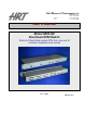
Hall Research Technologies, Inc Phone: Fax: 1163 Warner Ave. Tustin, CA 92780 (714) 641-6607 (714) 641-6698 User’s Manual Model MC4-H2 Dual Head KVM Switch Control 4 Dual Video output PC's from one set of monitors, keyboard and mouse April 11, 2006 UMA1091 Rev.
Table of Contents INTRODUCTION 2 GENERAL SUPPORTED SYSTEMS AND PERIPHERALS 2 2 FEATURES 2 SETUP 3 OPERATION 4 SWITCHING 4 SETTING THE ADDRESS OF THE MC4-H2 4 STACKING (DAISY-CHAINING) OF MULTIPLE MC4-H2 UNITS 5 HOT SWAPPING MICE AND KEYBOARDS 5 HOT SWAPPING PC’S 5 SPECIFICATIONS 6 FEDERAL COMMUNICATIONS COMMISSION (FCC) STATEMENT __________ 6 -1-
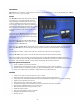
Introduction MC4-H2 allows two monitors, 1 keyboard, and 1 mouse to control 4 different PC’s or servers. By chaining up to 3 MC4H2’s, up to 12 PC’s can be controlled General The MC4-H2 switches both video outputs to display the selected PC’s video outputs at full resolution using buffered and wideband video circuits.
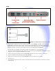
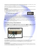
Setup FIGURE 1 MC4-H2 Connector Functions on Rear Panel FIGURE 2 CA-100872 Cable for connection to each PC 1. Use the special CA10087-6,or -10 (4-in-1) cable to connect PC A to the MC4-H2. The DB25 connector plugs into the MC4-H2. The keyboard connector, of the CA10087 cable is either labeled “K” or is purple and plugs into the keyboard port on PC A.
Operation The keyboard and mouse will function no differently than if the keyboard and mouse were connected directly to the PC. Switching You can use of three ways to switch among the PCs. The first way is to simply press the button for the desired PC on the front panel of the MC4-H2. The second way to switch is through a hot-key combination from the keyboard. The hot-key combination is as follows.
panel buttons to cycle the address from Master, to Slave 1, to Slave 2 and then back to Master. As the address cycles, you will see the port number on the front panel LED's changing between the following combinations: 1 2 3 4 or 5 6 7 8 or 9 10 11 12 When you have the proper address selected, press and hold down simultaneously the buttons of port A and port D on the unit. When the LED's stop blinking, this will indicate that the address has been set.
Specifications Dimensions Width X Height X Depth 19 X 1-3/4 X 5-1/4 in Single Rack Unit (1RU) construction Video Max Resolution 1600 X 1200 Coupling DC Video Level 0.7 V p-p Video Gain 1; double-terminated Bandwidth 250 MHz Drive 0 to 25 ft.
© Copyright 2006. Hall Research Technologies, Inc. All rights reserved. .. .. .. .. Hall Research Technologies, Inc. 1163 Warner Ave.