Trademarks & Copyright Windows 95/98/ME and Windows NT/2000/XP are registered trademarks of Microsoft Corp. All other brands and product names are trademarks of their respective companies. No part of this publication may be reproduced in any form or by any means or used to make any derivative (such as translation, transformation or adaptation) without the express written consent of the manufacturer as stipulated by the United States Copyright Act of 1976.
Package Contents Introduction Features Minimum Requirements Get to Know the Broadband Router Back Panel Front Panel Setup Diagram Getting Started 5 6 7 7 8 9 9 Chapter 1: Quick Setup (via web UI) About Quick Setup Step 1: Time Zone Step 2: Broadband Type 1.1 Cable Modem 1.2 Fixed IP xDSL 1.3 PPPoE 1.4 PPTP 18 18 19 20 21 22 24 Chapter 2: General Setup General Settings 2.1 System 2.1.1 Time Zone 2.1.2 Password Settings 2.1.3 Remote Management 2.2 WAN 2.2.1 Dynamic IP Address 2.2.2 Static IP Address 2.2.
2.4.6 ALG Settings 2.4.7 Static Routing 2.5 Firewall 2.5.1 Access Control 2.5.2 URL Blocking 2.5.3 DoS (Denial of Service) 2.5.4 DMZ Chapter 3: Status Status 3.1 Status and Information 3.2 Internet Connection 3.3 Device Status 3.4 System Log 3.5 Security Log 3.6 Active DHCP Client 3.7 Statistics 54 55 56 58 62 63 65 67 68 69 70 71 72 73 74 Chapter 4: Tools Tools 4.1 Configuration Tools 4.2 Firmware Upgrade 4.
The complete H2BR4 package consists of: • • One H2BR4 Dual WAN 4-Port Firewall Router One Quick Installation Guide • One CD with User’s Manual • • One Power Adapter Accessories Check to make sure that the unit was not damaged during shipping and that no items are missing. If you encounter a problem, please contact your dealer. Please read this manual thoroughly, and follow the installation and operation procedures detailed in this user’s manual.
The high performance Hawking H2BR4 Dual WAN Firewall Router with built-in 4-port 10/100M Ethernet Switch provides an easy-to-use, cost-effective means of sharing two broadband Internet connections with your LAN (Local Area Network). With the H2BR4’s two WAN ports, users experience significantly faster data rates as a result of increased and more efficient use of bandwidth. The dual WAN ports also provide: an easy way to utilize two different types of broadband Internet connections on the same network (i.e.
Minimum Requirements • One External xDSL (ADSL) or Cable modem with an Ethernet port (RJ-45) • Network Interface Card (NIC) for each Personal Computer (PC) • PCs with a Web-Browser (Internet Explorer 4.0 or higher, or Netscape Navigator 4.7 or higher) Note The WAN “idle timeout” auto-disconnect function may not work due to abnormal activities of some network application software, computer viruses or hacker attacks from the Internet.
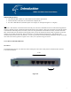
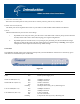
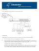
1) Local Area Network (LAN) The router’s four LAN ports are what you will use to connect your PCs, print servers, switches, etc. 2) Wide Area Network (WAN) The WAN ports are the segments that connect to your xDSL or Cable modems and are linked to the Internet. 3) Reset The Reset button allows you to do one of two things: i.
Setup Diagram Figure 1.2 below shows a typical setup for a Local Area Network (LAN). Figure 0.2 Getting started The following are step-by-step instructions on how to start using the router and get connected to the Internet. 1) Set up your network as shown in the setup diagram above (Figure 1.2). 2) You then need to set your LAN PC clients so that they can obtain an IP address automatically. All LAN clients require an IP address. Just like a street address, it allows LAN clients to find one another.
systems. For other operating systems (Macintosh, Sun, etc.), follow the manufacturer’s instructions. The following is a step-by-step illustration on how to configure your PC to obtain an IP address automatically for: 2a) Windows 95/98/Me, 2b) Windows 2000 and 2c) Windows NT. 2a) Windows 95/98/Me i: Click the Start button and select Settings, then click Control Panel. The Control Panel window will appear. ii: Double-click Network icon. The Network window will appear.
Figure 0.3 viii: Reboot the PC. Your PC will now obtain an IP address automatically from your router’s DHCP server. Note: Please make sure that the router’s DHCP server is the only DHCP server available on your LAN. Once you’ve configured your PC to obtain an IP address automatically, please proceed to Step 3. 2b) Windows 2000 i: Click the Start button and select Settings, then click Control Panel. The Control Panel window will appear. ii: Double-click the Network and Dial-up Connections icon.
Figure 0.4 vi: Click OK to confirm the settings. Your PC will now obtain an IP address automatically from your router’s DHCP server. Note: Please make sure that the router’s DHCP server is the only DHCP server available on your LAN. Once you’ve configured your PC to obtain an IP address automatically, please proceed to Step 3. 2c) Windows NT i: Click the Start button and select Settings, then click Control Panel. The Control Panel window will appear. ii: Double-click the Network icon.
iii: Check if the TCP/IP Protocol is on your list of Network Protocols. If TCP/IP is not installed, click the Add button to install it now. If TCP/IP is installed, go to step 5. iv: In the Select Network Protocol window, select the TCP/IP Protocol and click the Ok button to start installing the TCP/IP protocol. You may need your Windows CD to complete the installation. v: After you install TCP/IP, go back to the Network window.
vii: Click OK to confirm the settings. Your PC will now obtain an IP address automatically from your router’s DHCP server. Note: Please make sure that the router’s DHCP server is the only DHCP server available on your LAN. Once you’ve configured your PC to obtain an IP address automatically, please proceed to Step 3. 3) Once you have configured your PCs to obtain an IP address automatically, the router’s DHCP server will automatically give your LAN clients IP addresses.
6) The HOME page screen below will appear. The Home Page is divided into four sections, Quick Setup Wizard, General Setup, Status Information and Tools. Quick Setup Wizard (Chapter 1) If you only want to start using the router as an Internet Access device then you ONLY need to configure the screens in the Quick Setup Wizard section.
Menu Description Quick Setup Wizard (Chapter 1) Select your Internet connection type and then input the configurations needed to connect to your Internet Service Provider (ISP). General Setup (Chapter 2) This section contains configurations for the Broadband router’s advanced functions such as: Bridge, Address Mapping, Virtual Server, Access Control, Hacker Attack Prevention, DMZ, Special applications and other functions to meet your LAN requirements.
Figure 0.
About Quick Setup The Quick Setup section is designed to let you set up the router as quickly as possible. In the Quick Setup, you are required to fill in only the information necessary to access the Internet. Once you click on the Quick Setup Wizard in the homepage, you will see the screen below. Step 1) Time Zone The Time Zone allows your router to base its time on the settings configured here, this will affect functions such as Log entries and Firewall settings. Figure 1.
Click on NEXT to proceed to the next page (step 2). Step 2) Broadband Type In this section, you have to select one of four types of connections that you will be using to connect your router’s WAN port to your ISP (see screen below). Note: Different ISP’s require different methods of connecting to the Internet. Please check with your ISP as to the type of connection it requires. Figure 1.
Menu Description 1.1 Cable Modem Your ISP will automatically give you an IP address 1.2 Fixed-IP xDSL Your ISP has given you an IP address already 1.3 PPPoE Your ISP requires you to use a Point-to-Point Protocol over Ethernet (PPPoE) connection. 1.4 PPTP Your ISP requires you to use a Point-to-Point Tunneling Protocol (PPTP) connection. Click on one of the WAN types and then proceed to the manual’s relevant sub-section (1.1, 1.2, 1.3 or 1.4). Click on Back to return to the previous screen. 1.
Parameters Host Name Description If your ISP requires a Host Name, type in the host name provided by your ISP; otherwise leave it blank if your ISP does not require a Host Name. MAC Address Your ISP may require a particular MAC address in order for you to connect to the Internet. This MAC address is the PC’s MAC address that your ISP had originally connected your Internet connection to.
Parameters Description IP This is the IP address that your ISP has given you. Gateway IP This is the ISP’s IP address gateway DNS This is the ISP’s DNS server IP address Subnet Mask Enter the Subnet Mask provided by your ISP (e.g. 255.255.255.0) Click OK when you have finished the configuration above. You have now completed the configuration for the Fixed-IP xDSL connection. You can start using the router now.
Parameter Description User Name Enter the User Name provided by your ISP for the PPPoE connection Password Enter the Password provided by your ISP for the PPPoE connection Service Name This is optional. Enter the Service name should your ISP require it. Otherwise, leave it blank. MTU This is optional. You can specify the maximum size of your transmission packet to the Internet. Leave it as it is if you do not wish to set a maximum packet size.
1.4 PPTP Select PPTP if your ISP requires the PPTP protocol to connect you to the Internet. Your ISP should provide all the information required in this section. Figure 1.6 Parameter Description Obtain an IP address The ISP requires you to obtain an IP address by DHCP automatically before connecting to the PPTP server. Use the following IP address The ISP gives you a static IP to be used to connect to the PPTP server.
User ID Enter the User Name provided by your ISP for the PPTP connection (sometimes called a Connection ID). Password Enter the Password provided by your ISP for the PPTP connection. PPTP Gateway If your LAN has a PPTP gateway, then enter that PPTP gateway IP address here. If you do not have a PPTP gateway then enter the ISP’s Gateway IP address above. Connection ID This is the ID given by ISP. This is optional. MTU This is optional.
General Settings Once you click on the General Setup button on the homepage, you will see the screen below. If you have already configured the Quick Setup Wizard, you do NOT need to configure anything in the General Setup screen in order to start using the Internet. The General Setup contains advanced features that allow you to configure the router to meet your network’s needs such as: Address Mapping, Virtual Server, Access Control, Hacker Attack Prevention, Special Applications, DMZ and other functions.
Below is a general description of what advanced functions are available for this broadband router. Menu Description 2.1 System This section allows you to set the Broadband router’s system Time Zone, Password and Remote Management Administrator. 2.2 WAN This section allows you to select the connection method in order to establish a connection with your ISP (same as the Quick Setup Wizard section) 2.
Parameters System Settings Description 2.1.1 Time Zone Select the time zone of the country you are currently in. The router will set its time based on your selection. 2.1.2 Password Settings Allows you to select a password in order to access the web-based management website. 2.1.3 Remote Management You can specify a Host IP address that can perform remote management functions. Select one of the above three system settings selections and proceed to the manual’s relevant sub-sections. 2.1.
Parameter Description Set Time Zone Select the time zone of the country you are currently in. The router will set its time based on your selection. Time Server Address You can manually assign time server address if the default time server dose not work. Enable Daylight Savings The router can also take Daylight savings into account. If you wish to use this function, you must check/tick the enable box to enable your daylight saving configuration (below).
Parameters Current Password Description Enter your current password for the remote management administrator to log in to your router. Note: By default, the password is “1234” New Password Enter your new password Re-Enter Password for Verification Enter your new password again for verification purposes Note: If you forget your password, you will have to reset the router to the factory default (password is “1234”) with the reset button (see router’s back panel).
Parameters Description Host Address This is the IP address of the host on the Internet that will have management/configuration access to the Broadband router from a remote site. This means if you are at home and your home IP address has been designated the Remote Management host IP address for this router (located in your company office), then you are able to configure this router from your home. If the Host Address is left 0.0.0.
Figure 2.6 Parameters 2.2.1 Dynamic IP address Description Your ISP will automatically give you an IP address 2.2.2 Static IP address Your ISP has given you an IP address already 2.2.3 PPPoE Your ISP requires PPPoE connection. 2.2.4 PPTP Your ISP requires you to use a Point-to-Point Tunneling Protocol (PPTP) connection. 2.2.5 L2TP Your ISP requires L2TP connection. 2.2.6 Telstra Big Pond Your ISP requires Telstra Big Pond connection. 2.2.7 Policy You can configure WAN policy. 2.2.
2.2.1 Dynamic IP Address Choose the Dynamic IP selection if your ISP will give you an IP address automatically. Some ISP’s may also require that you fill in additional information such as Host Name, Domain Name and MAC address. (See Chapter 1: “Cable Modem” for more details.) 2.2.2 Static IP Address Choose the Static IP selection if your ISP has given you a specific IP address for you to use. Your ISP should provide all the information required in this section. (See Chapter 1: “Fixed IP” for more details.
Figure 2.
Parameter Description Obtain an IP address The ISP requires you to obtain an IP address by DHCP automatically before connecting to the L2TP server. MAC Address Your ISP may require a particular MAC address in order for you to connect to the Internet. This MAC address is the PC's MAC address that your ISP had originally connected your Internet connection to.
Idle Time Out Note: The WAN "idle timeout" auto-disconnect function may not work due to abnormal activities of some network application software, computer viruses or hacker attacks from the Internet. For example, some software sends network packets to the Internet in the background, even when you are not using the Internet. This function also may not work with some ISPs.
Parameter Description User Name Enter the User Name provided by your ISP for the Telstra Big Pond connection Password Enter the Password provided by your ISP for the Telstra Big Pond connection User decide login server server manually Select if you want to assign the IP of Telstra Big Pond’s login server manually. Login Server The IP of the Login Server. Click OK when you have finished the configuration above. You have now completed the configuration for the Telstra Big Pond connection.
Figure 2.9 Parameter Description Speed The send/upstream and receive/downstream speed of the WAN line the WAN port is connected to. Connectivity check You can key in an IP. The router will ping that IP to verify if the WAN line can access the Internet. You also can select “Ping Default Gateway”, and the router will check if the WAN line is ok by ping the default gateway of the WAN port. Operation If you select “Enable”, the WAN port will be activated when the system boot up.
dynamic IP settings, it is likely that the DNS server IP address is provided automatically. However, if there is a DNS server that you would rather use, you need to specify the IP address of that DNS server here. Figure 2.10 Parameters Description Domain Name Server (DNS) Server This is the ISP’s DNS server IP address that they gave you; or you can specify your own preferred DNS server IP address Secondary DNS Address (optional) This is optional.
Figure 2.
2.3 LAN The LAN Port screen below allows you to specify a private IP address for your router’s LAN ports as well as a subnet mask for your LAN segment. Figure 2.
Parameters LAN IP address IP Subnet Mask Default 192.168.2.1 255.255.255.0 Description This is the router’s LAN port (private) IP address (Your LAN clients’ default gateway IP address) Specifies a Subnet Mask for your LAN segment 802.1d Spanning Tree Disabled If the 802.1d Spanning Tree function is enabled, this router will use the spanning tree protocol to prevent network loops from occurring among the LAN ports. DHCP Server Enabled You can enable or disable the DHCP server.
2.4 NAT Network Address Translation (NAT) allows multiple users at your local site to access the Internet through a single Public IP Address or multiple Public IP Addresses. NAT provides Firewall protection from hacker attacks and has the flexibility to allow you to map Private IP Addresses to Public IP Addresses for key services such as Websites and FTP. You also can disable NAT function and use the static route. Figure 2.
2.4.1 Port Forwarding The Port Forwarding allows you to re-direct a particular range of service port numbers (from the Internet/WAN Ports) to a particular LAN IP address. It helps you to host some servers behind the router NAT firewall. Figure 2.
Parameter Description Enable Port Forwarding Enable Port Forwarding Private IP This is the private IP of the server behind the NAT firewall. Note: You need to give your LAN PC clients a fixed/static IP address for Port Forwarding to work properly. Type This is the protocol type to be forwarded. You can choose to forward “TCP” or “UDP” packets only or select “both” to forward both “TCP” and “UDP” packets. Port Range The range of ports to be forward to the private IP.
2.4.2 Virtual Server Use the Virtual Server function when you want different servers/clients in your LAN to handle different service/Internet application type (e.g. Email, FTP, Web server etc.) from the Internet. Computers use numbers called port numbers to recognize a particular service/Internet application type. The Virtual Server allows you to re-direct a particular service port number (from the Internet/WAN Port) to a particular LAN private IP address and its service port number.
Parameters Description Enable Virtual Server Enable Virtual Server. Private IP This is the LAN client/host IP address that the Public Port number packet will be sent to. Note: You need to give your LAN PC clients a fixed/static IP address for the Virtual Server function to work properly.
address for WAN 2. (For websites, you will need to have a fixed/static global/public IP address or use DDNS with dynamic IP and domain name mapping.) Figure 2.16 2.4.3 Special Applications Some applications require multiple connections, such as Internet games, video conferencing, Internet telephony and others. In this section you can configure the router to support multiple connections for these types of applications.
Figure 2.17 Parameters Description Enable Trigger Port Enables the Special Application function. Trigger Port This is the outgoing (Outbound) range of port numbers for this particular application Trigger Type Select whether the outbound port protocol is “TCP”, “UDP” or both. Public Port Enter the In-coming (Inbound) port or port range for this type of application (e.g. 23002400, 47624) Note: Individual port numbers are separated by a comma (e.g. 47624, 5775, 6541 etc.).
Popular applications This section lists the more popular applications that require multiple connections. Select an application from the Popular Applications selection. Once you have selected an application, select a location (1-10) in the Copy to selection box and then click the Copy to button. This will automatically list the Public Ports required for this popular application in the location (1-10) you had specified.
2.4.4 UPnP With UPnP, all PCs in your Intranet will discover/locate this router automatically. So you will not have to perform any configuration procedures for your PC and can access the Internet through this router easily. Figure 2.18 Parameters Default Description UPnP Feature Disable You can Enable or Disable the UPnP feature here.
2.4.5 Protocol and Port Binding Protocol and Port Binding let you manually bind an application to a WAN port. Only packets that match all the entered criteria will be bound to the assigned WAN port. You will have to fill all the items. The items that you leave blank will be ignored. Figure 2.19 Parameters Description Enable Protocol & Port Binding The “Protocol and Port Binding” function is disabled by default. You can select to enable the “Protocol and Port Binding” function.
Destination IP Range Only packets with this assigned destination IP range will statically bind to the assigned WAN port. Source Port Range Only packets with this assigned source port range will statically bind to the assigned WAN port. Destination Port Range Only packets with this assigned destination port range will statically bind to the assigned WAN port. Protocol Only packets with this assigned protocol will statically bind to the assigned WAN port.
2.4.6 ALG Settings You can select applications that need “Application Layer Gateway” to support. Figure 2.20 Parameters Enable Default Description You can enable the “Application Layer Gateway”. Then, the router will let that application correctly pass though the NAT gateway. Click Apply at the bottom of the screen to save the above configurations. You can now configure other advanced sections or start using the router (with the advanced settings in place).
2.4.7 Static Routing This router provides a Static Routing function when NAT is disabled. With Static Routing, the router can forward packets according to your routing rules. Note: The DMZ function of the firewall will not work if static routing is enabled. Figure 2.21 Parameter Description Enable Static Routing The Static Routing function is disabled by default. You have to enable the Static Routing function before your routing rules take effect.
Hop Count The number of hops (routers) to pass through to reach the destination LAN. Interface The interface that goes to the next hop (router). Add a Rule Fill in the "Destination LAN IP", "Subnet Mask”, “Default Gateway”, "Hop Count" and "Interface" of the rule to be added and then click "Add". This rule for Static Routing will then be added into the "Static Routing Table" below. If you find any errors before adding it and want to retype it again, just click "Clear" and the fields will be cleared.
Figure 2.23 Parameters Description 2.5.1 Access Control Access Control allows you to specify which hosts/users can have access to certain Internet applications. 2.5.2 URL Blocking URL Blocking allows you to specify which URLs cannot be accessed by users. 2.5.3 DoS The router's firewall can block common hacker attacks and can log the attack activities. 2.5.4 DMZ The DMZ function allows you to re-direct all packets going to your WAN port IP address to a particular IP address in your LAN.
2.5.1 Access Control If you want to restrict users from accessing certain Internet applications/services (e.g. Internet websites, email, FTP etc.), you can change the relevant settings here. Access Control allows users to define the type of traffic permitted on your LAN. You can control which PC client can have access to these services. Figure 2.24 Parameters Description Filter client PCs by IP Fill “IP Filtering Table” to filter PC clients by IP.
Add PC Fill in “Client PC MAC Address” and “Comment” for the PC that will be allowed to access the Internet, and then click “Add”. If you find any errors before adding it and want to retype it again, just click "Reset" and the fields will be cleared. Remove PC If you want to remove a PC from the "MAC Filtering Table", select the PC you want to remove in the table and then click "Delete Selected". If you want to remove all PCs from the table, just click the "Delete All" button.
Add PC Parameters Client PC Description Description The description for this client PC rule. Client PC IP Address Enter the IP address that you wish to apply the Access Control rule to. This is the user’s IP address for which you wish to setup an Access Control rule. Note: You need to give your LAN PC clients a fixed/static IP address for the Access Control rule to work properly.
Example: Access Control In the example below, LAN client A can only access websites that use Port 80. However, LAN client B is able to access websites and any other service that uses ports between 80 and 999. Figure 2.
2.5.2 URL Blocking You can block access to some Web sites from particular PCs by entering a full URL address or just a keyword of the web site. Figure 2.27 Parameters Description Enable URL Blocking Enables/disables URL Blocking. Add URL Keyword Fill in the “URL/Keyword” and then click “Add”. You can enter the full URL address or the keyword of the web site you want to block. If you find any errors before adding it and want to retype it again, just click "Reset" and the field will be cleared.
2.5.3 DoS (Denial of Service) The Broadband router's firewall can block common hacker attacks, including Ping of Death, Discard Ping from WAN, Port Scan, and Sync Flood. If Internet attacks occur the router can log the events. Figure 2.
Figure 2.29 Parameters Intrusion Detection Features Description Ping of Death Protections from Ping of Death attacks. From the Advanced Settings page, you can configure a threshold for the frequency of packet occurrence. Discard Ping From WAN The router’s WAN port will not respond to any Ping requests Port Scan Protection from any Port Scan attacks. If you go to the Advanced Settings page, you can configure the pattern of Port Scan you want to prevent.
2.5.4 DMZ If you have a local client PC that cannot run an Internet application (e.g. Games) properly from behind the NAT firewall, then you can open the client up to unrestricted two-way Internet access by defining a DMZ Host. The DMZ function allows you to re-direct all packets going to your WAN port IP address to a particular IP address in your LAN. The difference between the virtual server and the DMZ function is that the virtual server re-directs a particular service/Internet application (e.g.
Parameters Enable DMZ Description Enables/disables DMZ. Note: If there is a conflict between the Virtual Server and the DMZ setting, then the Virtual Server function will have priority over the DMZ function. WAN Port The WAN port that the local client PC’s IP address will bind to. Public IP Address The IP address of the WAN port or any other Public IP addresses given to you by your ISP. The WAN port may use dynamic IP or static IP given by your ISP.
Status The Status section allows you to monitor the current status of your router. You can use the Status page to monitor: the connection status of the router's WAN/LAN interfaces, the current firmware and hardware version numbers, any illegal attempts to access your network, and information on all DHCP client PCs currently connected to your network. Parameters Description 3.1 Status and Information Shows the router’s system information 3.
3.1 Status and Information The Status and Information section allows you to view the router’s system information. Figure 3.
3.2 Internet Connection View the router’s current Internet connection status and other related information. Figure 3.2 Parameters Description Internet Connection This page displays whether the WAN ports are connected to Cable/DSL connections. It also displays the router’s WAN port: WAN IP address, Subnet Mask, and ISP Gateway as well as the Primary DNS and Secondary DNS being used.
3.3 Device Status View the router’s current configuration settings. The Device Status displays the configuration settings you have configured in the Quick Setup Wizard/General Setup section. Figure 3.3 Parameters Description Device Status This page shows the router’s current device settings. This page displays the router LAN port’s current LAN IP Address and Subnet Mask. It also shows whether the DHCP Server is enabled.
3.4 System Log View the operation log of the system. Figure 3.4 Parameters Description System Log This page shows the current system log of the Broadband router. It displays any event occurred after system start up. At the bottom of the page, the system log can be saved to a local file for further processing, or the system log can be cleared , or it can be refreshed to get the most updated status.
3.5 Security Log View any attempts that have been made to illegally gain access to your network. Figure 3.5 Parameters Description Security Log This page shows the current security log of the Broadband router. It displays any illegal attempts to access your network. At the bottom of the page, the security log can be saved to a local file for further processing, or the security log can be cleared , or it can be refreshed to get the most updated status.
3.6 Active DHCP Client View your LAN client's information that is currently linked to the Broadband router's DHCP server Figure 3.6 Parameters Description DHCP Client Log This page shows all DHCP clients (LAN PCs) currently connected to your network. The “Active DHCP Client Table” displays the IP address and the MAC address and Time Expired for each LAN Client. Use the Refresh button to get the most updated status.
3.7 Statistics View the statistics of packets sent and received over each WAN and LAN interface. Figure 3.7 Parameters Description Statistics Shows the counters for packets sent and received over the WAN and LAN interfaces.
Tools This page includes the basic configuration tools, such as Configuration Tools (save or restore configuration settings), Firmware Upgrade (upgrade system firmware) and Reset. Figure 4.1 Parameters Description 4.1 Configuration Tools You can save the router’s current configuration, restore the router’s saved configuration files and restore the router’s factory default settings. 4.2 Firmware Upgrade This page allows you to upgrade the router’s firmware. 4.
4.1 Configuration Tools The Configuration Tools screen allows you to save (back up) the router’s current configuration settings. Saving the configuration settings provides an added protection and convenience if problems occur with the router and you have to reset to the factory default. When you save (back up) the configuration settings, you can re-load the saved configuration into the router through the Restore selection.
4.2 Firmware Upgrade This page allows you to upgrade the router’s firmware Figure 4.3 Parameters Description Firmware Upgrade This tool allows you to upgrade the router’s system firmware. To upgrade your router’s firmware, you need to download the firmware file to your local hard disk, and enter that file name and path in the appropriate field on this page. You can also use the Browse button to find the firmware file on your PC.
4.3 Reset You can reset the router’s system if any problems occur. The reset function essentially re-boots your router’s system. Figure 4.4 Parameters Description Reset In the event that the system stops responding correctly or in some way stops functioning, you can perform a reset. Your settings will not be changed. To perform the reset, click on the APPLY button. You will be asked to confirm your decision. The reset will be complete when the power light stops blinking.
How to Manually Find Your PC’s IP and MAC Addresses 1) In Windows, open the Command Prompt program. 2) Type Ipconfig /all and click Enter. • • • Your PC’s IP address is the one entitled IP address (192.168.1.77) The router’s IP address is the one entitled Default Gateway (192.168.1.
Bridge: A bridge is an intelligent, internetworking device that forwards or filters packets between different networks based on data link layer (MAC) address information. Default Gateway (Router): Every non-router IP device needs to configure a default gateway’s IP address. When the device sends out an IP packet, if the destination is not on the same network, the device has to send the packet to its default gateway, which will then send it out towards the destination.
ISP Gateway Address: (see ISP for definition). The ISP Gateway Address is an IP address for the Internet router located at the ISP's office. ISP: Internet Service Provider. An ISP is a business that provides connectivity to the Internet for individuals and other businesses or organizations. LAN: Local Area Network. A LAN is a group of computers and devices connected together in a relatively small area (such as a house or an office). Your home network is considered a LAN.
Protocol: A protocol is a set of rules for interaction agreed upon between multiple parties so that when they interface with each other based on such a protocol, the interpretation of their behavior is well defined and can be made objectively, without confusion or misunderstanding. Router: A router is an intelligent network device that forwards packets between different networks based on network layer address information such as IP addresses.