
User Manual
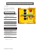

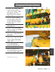
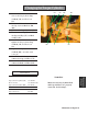

21. Use the 1" and 1 1/8" wrench to
connect the Rod side Hose (RH)
and the Cap side Hoses (CH1),
(CH2).
22. Insert the Torque Cylinder Rod
Pin (P).
23. Insert the Torque Cylinder
Safety Clip (SC).
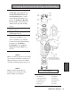
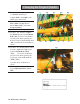
24. Make sure no bodily parts are
in the retract path of the Torque
Cylinder. Turn on the
hydraulic power unit. Pull out
the “E” stop. The Middle
wrench will retract.
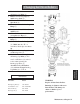
Part Numbers
Part Name Part #
Mount Bolt (TBH) 999-806542-1
Mount Bolt (TBA) 999-806542
Mount Bolt (BB) 999-806529
Lock Washers 061- 91074A036
Safety Clip (SC) 061- 98335A114
Torque Cylinder Rod Pin (P) 061-20204A
Torque Cylinder (C) 061-H17
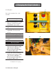
WARNING
Make sure the Torque Cylinder
Rod and Cap side Hoses are
properly connected.
WARNING
Make sure the Low Torque
Warning System Hydraulic Hoses
are securely connected.
Maintenance & Repair 57
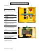
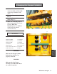
Changing the Torque Cylinder
CH2
CH1 RH P
SC
E