Introduction Table of Contents Warranty OPERATION, MAINTENANCE AND SERVICE MANUAL Drawings 1245 East 23rd Street Long Beach, CA 90806 Phone: 562-424-0709 Fax: 562-490-9959 Trouble Shooting HAWK INDUSTRIES, INC.
Introduction Hawk's design philosophy is simple: Design with the end user in mind. Make it tough, dependable and easy to maintain. Hawk has designed the HawkJaw with this same simple formula. FEATURES The HawkJaw 65K-ALS is a hanging unit that will spin, make up and break out drill pipe. It is revolutionary because the tool spins and makes up drill pipe or breaks out and spins drill pipe in 12 seconds or less. A patented self-energized grip system provides consistent torque values to the drill string.
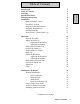
Table of Contents 2 3 6 7 8 9 9 9 10 11 12 13 Operation Start-up Procedure Adjust for Make Up Adjusting the Wrenches Adjusting the Spinner Shift Spinner for Make Up Position for Make Up Setting Make Up Torque Make Up Adjust for Break Out Adjusting the Wrenches Adjusting the Spinner Shift Spinner for Break Out Position for Break Out Break Out Notes 14 14 15 15 16 18 19 21 22 23 23 24 26 27 29 30 Maintenance & Repair Wrench Maintenance Die Pivot Blocks Wrench Hook Wrench Nut Hook Pivot Bearing Cap Grip Cyl
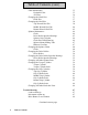
Table of Contents (cont.
Table of Contents (cont.
Warranty HAWKJAW 65K-ALS & 100K-ALS STANDARD WARRANTY AND FIELD SERVICE Your Hawkjaw must be free of material and workmanship defects for a period of six months from the date of delivery. If any items fail because of a manufacturing defect within that period of time, that item will be replaced by Hawk Industries. Hawk Industries at its discretion may extend this warranty period. Replacement of parts will be accomplished either at the factory or at a designated service point.
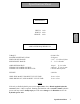
Specification Sheet DIMENSIONS Specification Sheet DEPTH: 34 in. WIDTH: 40 in. HEIGHT: 90 in. PERFORMANCE AND POWER REQUIREMENTS TORQUE: MAXIMUM PIPE ROTATION: WRENCH SIZE RANGE: SPINNER SIZE RANGE: 65,000 ft. lbs. 50 degrees 3 1/2" __ 8" OD tool joints 3" __ 5 1/2" OD tube AIR POWER SOURCE: HYDRAULIC POWER SOURCE: HYDRAULIC POWER SOURCE TYPE: 100 psi @ 2-10 cfm 2,600 psi @ 20-35 gpm Closed Center System WEIGHT: 2,200 lbs.
Ordering Instructions All parts must be ordered by giving the quantity required, the full part number as listed in this manual under Part #, the unit serial number, the model number and part name.
Hanging Cable Location 1. Anchor the hanging cable to a point as close to the derrick crown as possible. The longer the hanging cable, the easier the HawkJaw is to move on and off the drill pipe. 2. Locate the cable hang point as high above the center of the rotary table as possible. The cable must hang within 2'-4' ft. of the rotary table center.
Hanging Cable Requirements 1. 2. 3. 4. 5/8" diameter steel cable. Appropriate hanging cable hardware for 5/8" diameter steel cable. Enough cable length to suspend the Hanger Eye (HE) 20' ft. above the rig floor. Enough cable length to allow the HawkJaw to rest on the rig floor 3'- 5' ft. away from the rotary table with the lift cylinder completely stroked out. The lift cylinder is 13' ft. long when completely stroked out.
Hydraulic Requirements 1. Pressure compensated pump set to pressure compensate at 2600 psi. 2. Minimum volume of 20 gpm. 35 gpm for top performance. 3. 1" minimum Pressure line. 1 1/4" Pressure line if the power unit is located more than 100' apart from the HawkJaw. The hose working pressure must be 3000 psi or greater. 4. 1 1/4" minimum Tank line. 500 psi minimum hose working pressure. 5. Hawk approved pressure side non-collapsible type 3000 psi filter (Part # 061-H25).
Air Requirements 1. Clean, dry air at 100 psi @ a negligible volume. 2. On board auto-dump air filter (AF) (part# 061-A22), located on board the rear of the Hawkjaw. 3. Auto-dump air filter* (Part # 061-J29), must be installed in-line between the air source and the HawkJaw. Initial filter supplied with the HawkJaw. 4. Enough slack in the line for the HawkJaw to move from its rest position to the drill pipe connection to the mouse hole connection. WARNING The HawkJaw must receive clean, dry air.
Raise/Lower Cylinder Hook - Up 1. Use the Raise/Lower cylinder Cap side Bolt (B) to connect the HawkJaw Suspension Ring (SR) to the Raise/Lower cylinder (C). 2. Use the Raise/Lower cylinder Cap side Lock Nut (N) to secure the Raise/Lower cylinder Cap side Bolt (B). 3. Connect the Hanger Eye (HE) to the hanging cable. 4. Connect the HawkJaw Rod side (HR) and Cap side (HC) hydraulic Leader hoses to the Raise/Lower cylinder Rod side (RR) and Cap side (RC) hoses. NOTE NOTE Tightly connect the hose fittings.
Start-up Procedure 1. Connect the air power source with the Air (A) line. 2. Make sure the hydraulic reservoir is full. 3. Connect the hydraulic Pressure (P), Tank (T) and Air (A) lines. "P" and "T" Port Designations are stamped on the Main Hydraulic Manifold (M). 4. Check for hydraulic leaks. If leaks occur, see Trouble Shooting, p. 67. 5. No motion should occur. If there is movement of any parts on the HawkJaw, see Trouble Shooting, p. 67-69. NOTE Tightly connect the hose fittings.
Adjust for Make Up Adjusting the Wrenches Tools Required OD calipers, 1 1/2" wrench NL 1. Make sure the nut lock (NL) is in the unlocked position. Adjusting the Nut Lock Detent Setting (If Needed) A. Loosen the jam nut (J) to allow some space for the arm to adjust. B. Screw the arm (A) in or out to adjust the stiffness of the springloaded detent (SD). C. Tighten the jam nut (J) to secure the arm (A) from loosening.
Adjust for Make Up 2. Measure the tool joint with OD calipers. 3. Use the 1 1/2" wrench to adjust the Pointer (P) on the Pipe stop index (PI) to the OD tool joint size. Its always better to adjust the pointer 1/4" to 1/2" larger than the measured diameter of the tool joint. 4. For safety, adjust the Bottom wrench nut (BN) 1" larger than the Top wrench nut (TN) and Middle wrench nut (MN). 5. Rotate the Top wrench nut (TN) and the Middle wrench nut (MN) to the OD tool joint size.
Adjust for Make Up Adjusting the Spinner Tools Required OD calipers QR 1. Measure the drill pipe tube with OD calipers. 2. Tube Size Use 4 1/2"- 5 1/2" Front Holes (FH) 3 1/2"- 4" Middle Holes (MH) 2 7/8" Rear Holes (RH) 3. Remove the two quick release pins (QR). 4. Slide the whole Drive unit (D) forward or backward to the appropriate holes. 5. Replace the quick release pins (QR). D Continued on next page.
Adjust Spinner for Make Up (cont.) 6. Use the rotary table to spin drill collars larger than 5 1/2" OD. Place the HawkJaw spinner in the rest position. Rest Position 1. Remove the Spinner Arm Pins (P). 2. Rotate the Spinner back to the Pullback position (R). 3. Insert the Spinner Arm Pins (P) with retainer clips.
Shift Spinner for Make Up 1 Shift spinner directional valve (SDV) fully forward to the make position as shown.
Position for Make Up 1. Stab the drill stand. 2. Center the Suspension Ring (SR) on the Lateral tilt screw (LTS). 3. If the HawkJaw rests on the rig floor, use Raise (R) to raise the HawkJaw 1'- 2' ft. off the rig floor. 4. If the HawkJaw is hooked back to the derrick, unhook the HawkJaw. 5. Use the Control Handles (CH) to pull the HawkJaw onto the drill pipe connection. 6. Use Raise (R) and Lower (L) to center the Top wrench dies (TD) and the Middle wrench dies (MD) between the shoulder (S). 7.
Position for Make Up (cont.) 9. Check that the HawkJaw Top wrench (TW), Middle wrench (MW) and Bottom wrench (BW) hang straight and level when the drill pipe is against the pipe stop. 10. If the HawkJaw wrenches (TW, MW, BW) hang tilted forward or backward, use the crescent wrench to adjust the Turnbuckle (TB). 11. If the HawkJaw wrenches (TW, MW, BW) hang sloped to the right or to the left, use the Control Handles (CH) to back the HawkJaw off the pipe. Use Lower (L) to lower the HawkJaw to the rig floor.
Setting Make Up Torque RN RNA TN Shown set for 30,000 ft. lbs. G Operation 1. Follow the steps on pages 14-21. 2. Use the Red needle adjust (RNA) to rotate the Torque gauge red needle (RN) to the desired torque. 3. Rotate the Torque Set knob (K) counter- clockwise as far as the Torque Set knob (K) will turn. 4. Press and hold Spin (S) until the stand rotates down to the shoulder. 5. Release Spin (S). 6. Push in the wrench Grip (G). 7. Press and hold Torque (T).
Make Up RN 1. Follow the steps on pages 14-21. 2. Press and hold Spin (S) until the stand rotates down to the shoulder. 3. Release Spin (S). 4. Push in the wrench Grip (G). 5. Push and hold down Torque (T). 6. Watch the Torque gauge needle (TN). 7. When the Torque gauge needle rises above and settles at the desired torque (this rising above is a normal hydraulic adjustment), release Torque (T). Immediately release the Middle wrench Grip (MG). 8. Release Torque (T). Immediately release the wrench Grip (G).
Adjust for Break Out Adjusting the Wrenches Tools Required OD calipers, 1 1/2" wrench NL 1. Make sure the nut lock (NL) is in the unlocked position. Adjusting the Nut Lock Detent Setting (If Needed) A. Loosen the jam nut (J) to allow some space for the arm to adjust. B. Screw the arm (A) in or out to adjust the stiffness of the springloaded detent (SD). C. Tighten the jam nut (J) to secure the arm (A) from loosening.
Adjust for Break Out 2. Measure the tool joint with OD calipers. 3. Use the 1 1/2" wrench to adjust the Pointer (P) on the Pipe stop index (PI) to the OD tool joint size. Its always better to adjust the pointer 1/4" to 1/2" larger than the measured diameter of the tool joint. 4. For safety, adjust the Bottom wrench nut (BN) 1" larger than the Top wrench nut (TN) and Middle wrench nut (MN). 5. Rotate the Top wrench nut (TN) and the Middle wrench nut (MN) to the OD tool joint size.
Adjust for Break Out Adjusting the Spinner Tools Required OD calipers QR 1. Measure the drill pipe tube with OD calipers. 2. Tube Size Use 4 1/2"- 5 1/2" Front Holes (FH) 3 1/2"- 4" Middle Holes (MH) 2 7/8" Rear Holes (RH) 3. Remove the two quick release pins (QR). 4. Slide the whole Drive unit (D) forward or backward to the appropriate holes. 5. Replace the quick release pins (QR). D Continued on next page.
Adjust Spinner for Break Out (cont.) 6. Use the rotary table to spin drill collars larger than 5 1/2" OD. Place the HawkJaw spinner in the rest position. Rest Position 1. Remove the Spinner Arm Pins (P). 2. Rotate the Spinner back to the Pullback position (R). 3. Insert the Spinner Arm Pins (P) with retainer clips.
Shift Spinner for Break Out 1 Shift spinner directional valve (SDV) fully rearward to the break position as shown.
Position for Break Out 1. Stab the drill stand. 2. Center the Suspension Ring (SR) on the Lateral tilt screw (LTS). 3. If the HawkJaw rests on the rig floor, use Raise (R) to raise the HawkJaw 1'- 2' ft. off the rig floor. 4. If the HawkJaw is hooked back to the derrick, unhook the HawkJaw. 5. Use the Control Handles (CH) to pull the HawkJaw onto the drill pipe connection. 6. Use Raise (R) and Lower (L) to center the Middle wrench dies (MD) and the Bottom wrench dies (BD) between the shoulder (S). 7.
Position for Break Out (cont.) TW 9. Check that the HawkJaw Top wrench (TW), Middle wrench (MW) and Bottom wrench (BW) hang straight and level when the drill pipe is against the pipe stop. 10. If the HawkJaw wrenches (TW, MW, BW) hang tilted forward or backward, use the crescent wrench to adjust the Turnbuckle (TB). 11. If the HawkJaw wrenches (TW, MW, BW) hang sloped to the right or to the left, use the Control Handles (CH) to back the HawkJaw off the pipe.
Break Out G S T Operation 1. Follow the steps on pages 14, 2430. 2. Push in the wrench Grip (G). 3. Push and hold down Torque (T). 4. When break out occurs, release Torque (T). Immediately release the wrench Grip (G). 5. If the connection does not break out, continue to hold down Torque (T) and get another crew person to rotate the Torque Set knob (K) clockwise until the connection breaks out. When break out occurs, release Torque (T). Immediately release the wrench Grip (G). 6.
Notes 32 Operation
Wrench Maintenance Grease Once per Trip D2 D1 Tools Required Grease gun Initial Steps 1. Make sure the HawkJaw is off the drill pipe connection and in the rest position on the derrick. 2. Shut down the Hydraulic power unit. 3. Press, push, and pull all control buttons repeatedly to bleed hydraulic pressure. 4. Disconnect the Air power supply. 5. Press, push, and pull all control buttons repeatedly to bleed air pressure. 6. Assume that there is still a load on every actuator. Proceed with caution.
Wrench Maintenance Grease Once per Week NS N T Wrench Hook 1. Surface grease the hook thread (T) on the top wrench, middle wrench, and bottom wrench. 2. Rotate the wrench nut (N) on the top wrench, middle wrench, and bottom wrench to spread grease on the full thread area. Wrench Nut 1. Surface grease the wrench nut surface (NS) on the top wrench, middle wrench, and bottom wrench. Hook Pivot Bearing Cap 1. Pump the Hook pivot bearing cap grease fitting (H) on the top and bottom of each wrench.
Wrench Maintenance Grease Once per Week G2 G1 G3 G4 Tools Required Grease gun Initial Steps 1. Make sure the HawkJaw is off the drill pipe connection and in the rest position on the derrick. 2. Shut down the Hydraulic power unit. 3. Press, push, and pull all control buttons repeatedly to bleed hydraulic pressure. 4. Disconnect the Air power supply. 5. Press, push, and pull all control buttons repeatedly to bleed air pressure. 6. Assume that there is still a load on every actuator. Proceed with caution.
Wrench Maintenance Grease Twice per Year MP2 MP1 Tools Required Grease gun Initial Steps 1. Make sure the HawkJaw is off the drill pipe connection and in the rest position on the derrick. 2. Shut down the Hydraulic power unit. 3. Press, push, and pull all control buttons repeatedly to bleed hydraulic pressure. 4. Disconnect the Air power supply. 5. Press, push, and pull all control buttons repeatedly to bleed air pressure. 6. Assume that there is still a load on every actuator. Proceed with caution.
Hydraulic Filter Maintenance Change Every 2 Months Initial Steps 1. Depress the Red button (RB) located under the See-through rubber weather cap (SC). 2. Operate the HawkJaw. 3. If the Red button pops up, proceed with Step 4. 4. Make sure the HawkJaw is off the drill pipe connection and in the rest position on the derrick. 5. Shut down the Hydraulic power unit. 6. Press, push, and pull all control buttons repeatedly to bleed hydraulic pressure. 7. Disconnect the Air power supply. 8.
Air Filter Maintenance Change Every 2 Months Initial Steps CB 1. Disconnect the Air power supply. 2. Bleed Air Pressure. FC S Air Filter 1. Remove the two right Corner bolts (CB). 2. Slide out the Second stage filter cartridge (SC) and Star spacers (S). 3. Slide out the First stage filter cartridge (FC) and Star spacers (S). 4. Slide in the new First stage Filter cartridge and Star spacers (S). 5. Slide in the new Second stage filter cartridge and Star spacers (S). 6.
Changing the Hook Dies B Tools Required 3/4" wrench, See Drawings p. 128. Initial Steps 1. Make sure the HawkJaw is off the drill pipe connection and in the rest position on the derrick. 2. Shut down the Hydraulic power unit. 3. Press, push, and pull all control buttons repeatedly to bleed hydraulic pressure. 4. Disconnect the Air power supply. 5. Press, push, and pull all control buttons repeatedly to bleed air pressure. 6. Assume that there is still a load on every actuator. Proceed with caution.
Changing the Heel Dies Tools Required 3/4" wrench, See Drawings p. 128. Initial Steps 1. Make sure the HawkJaw is off the drill pipe connection and in the rest position on the derrick. 2. Shut down the Hydraulic power unit. 3. Press, push, and pull all control buttons repeatedly to bleed hydraulic pressure. 4. Disconnect the Air power supply. 5. Press, push, and pull all control buttons repeatedly to bleed air pressure. 6. Assume that there is still a load on every actuator. Proceed with caution.
Changing the Heel Dies (cont.) 7. Make sure the back and sides of the new Die are clean. 8. Grease the back of the new Die. 9. Insert the new Die into the Die Holder (DH) with the teeth of the Die facing out. 10. Place the Die Holder (DH) back in the Die Pivot Block (DB). 11. Insert the Heel Die Pin (P). 12. Replace the Heel Die Rollers (R). 13. Replace the Roller Bushings (RB). 14. Use the 3/4" wrench to replace the Heel Die Roller Bolts (B) and Lock Washers.
Changing the Heel Dies (cont.) Tools Required 3/4" wrench, See Drawings p. 128. Initial Steps 1. Make sure the HawkJaw is off the drill pipe connection and in the rest position on the derrick. 2. Shut down the Hydraulic power unit. 3. Press, push, and pull all control buttons repeatedly to bleed hydraulic pressure. 4. Disconnect the Air power supply. 5. Press, push, and pull all control buttons repeatedly to bleed air pressure. 6. Assume that there is still a load on every actuator. Proceed with caution.
Changing the Heel Dies (cont.) 6. Slide out the worn Die (D). 7. Make sure the back and sides of the new Die are clean. 8. Grease the back of the new Die. 9. Insert the new Die into the Die Holder (DH) with the teeth of the Die facing out. 10. Place the Die Holder (DH) back in the Die Pivot Block (DB). 11. Insert the Heel Die Pin (P). 12. Replace the Roller Bushings (RB). 13. Replace the Heel Die Rollers (R). 14. Use the 3/4" wrench to replace the Heel Die Roller Bolts (B) and Lock Washers.
Changing the Heel Dies (cont.) Tools Required B 3/4" wrench, See Drawings p. 128. Initial Steps 1. Make sure the HawkJaw is off the drill pipe connection and in the rest position on the derrick. 2. Shut down the Hydraulic power unit. 3. Press, push, and pull all control buttons repeatedly to bleed hydraulic pressure. 4. Disconnect the Air power supply. 5. Press, push, and pull all control buttons repeatedly to bleed air pressure. 6. Assume that there is still a load on every actuator.
Changing the Heel Dies (cont.) 6. Grease the back of the new Die. 7. Insert the new Die into the Die Holder (DH) with the teeth of the Die facing out. 8. Place the Die Holder (DH) back in the Die Pivot Block (DB). 9. Insert the Heel Die Pin (P). 10. Use the 3/4" wrench to replace the Heel Die Bolts (B) and Lock Washers.
Spinner Maintenance Grease Once per Week B Lubricant Required Chevron Pinion Grease Spray (Part # MS-SP), 7/16" wrench Chain 1. Connect the air and hydraulic power units to the HawkJaw. See Operation, p. 14. 2. Use the 7/16" wrench to remove the rubber Safety shield bolts (B). 3. Remove rubber Safety shield (S). 4. While spinning after break out, from the back of the spinner, apply spray to chain. 5. Replace rubber Safety shield (S). 6. Use the 7/16" wrench to replace the rubber Safety shield bolts (B).
Spinner Maintenance Grease Once per Month G1 G2 Tools Required Grease gun, 7/16" wrench Initial Steps 1. Make sure the HawkJaw is off the drill pipe connection and in the rest position on the derrick. 2. Shut down the Hydraulic power unit. 3. Press, push, and pull all control buttons repeatedly. 4. Disconnect the Air power supply. 5. Press, push, and pull all control buttons repeatedly. 6. Assume that there is still a load on every actuator. Proceed with caution.
Spinner Maintenance TC Grease Once per Month Tools Required Grease gun Spinner Grip Cylinders 1. Pump grease fitting SC1-SC2 on the Top spinner grip cylinder (TC) and the Bottom spinner grip cylinder (BC). Chain Drive Shaft Bearing BC 1. Pump grease fitting CB1.
Spinner Maintenance P Grease Once per Month Tools Required Grease gun Spinner Mount Sliding Tube 1. Pump grease fittings ST1-ST4. Check Oil Level Once per Month Lubricant Required # 32 weight gear oil Reducer Gear Box 1. Make sure the gear box oil level reaches the top pipe plug (P). NOTE Consistent lubrication of the Spinner increases performance and component life.
Changing the Spinner Chain Tools Required 7/16" wrench, Hammer, Needle-Nose Pliers Initial Steps 1. Make sure the HawkJaw is off the drill pipe connection and in the rest position on the derrick. 2. Shut down the Hydraulic power unit. 3. Press, push, and pull all control buttons repeatedly to bleed hydraulic pressure. 4. Disconnect the Air power supply. 5. Assume that there is still a load on every actuator. Proceed with caution. SD QR Chain 1. Make sure the Spinner doors (SD) are open. 2.
Changing the Spinner Chain (cont.) H 8. From the front of the unit, use the Needle-nose pliers to remove the Cotter pins (CP) in one of the Chain links. 9. Use the hammer to remove the Chain link pin (CLP). 10. Pull out the old chain. Make sure the chain does not catch on the Drive sprocket (DS). 11. Feed the chain into the spinner behind the Drive Sprocket (DS) until both ends of the new chain meet at the roller sprockets (DRS). 12.
Changing the Drive Rollers Tools Required 3/4" wrench Initial Steps 1. Make sure the HawkJaw is off the drill pipe connection and in the rest position on the derrick. 2. Shut down the Hydraulic power unit. 3. Press, push, and pull all control buttons repeatedly to bleed hydraulic pressure. 4. Disconnect the Air power supply. 5. Assume that there is still a load on every actuator. Proceed with caution. Drive Rollers 1. Use the 3/4" wrench to remove all Bearing Cap Bolts (1). 2.
Changing the Drive Rollers (cont.) 8. Slide in the Drive Roller Sprockets (17) . Make sure the "T" on each Drive Roller Sprocket faces up. 9. Replace the Bearing Caps (3) and Bearing Seals (5). 10. Use the 3/4" wrench to replace all Bearing Cap Bolts (1). Use new Lock Washers (2) and red loctite when replacing the Bearing Cap Bolts (1). Assemble the Lock Washers (2) as shown. Torque Bearing Cap Bolts (1) to 75 lb. ft.
Changing the Drive Roller Sprocket Bearings Tools Required Four 1/4"-20 x 1 1/2" Hex Tap SS (Part # 999-805867), 7/16" wrench, 3/ 4" wrench Initial Steps 1. Make sure the HawkJaw is off the drill pipe connection and in the rest position on the derrick. 2. Shut down the Hydraulic power unit. 3. Press, push, and pull all control buttons repeatedly to bleed hydraulic pressure. 4. Disconnect the Air power supply. 5. Assume that there is still a load on every actuator. Proceed with caution.
Changing the Drive Roller Sprocket Bearings (cont.) pushed out. Tighten the Hex Tap screws evenly, or the bearing (4) will tilt and lodge in the bearing cap (3). 5. Insert the new bearings into the Bearing Caps (3). 6. Replace the Bearing Caps (3) and Bearing Seals (5). 7. Use the 3/4" wrench to replace all Bearing Cap Bolts (1). Use new Lock Washers (2) and Red Loctite when replacing the Bearing Cap Bolts (1). Assemble the Lock Washers (2) as shown. Torque Bearing Cap Bolts (1) to 75 lb. ft.
Changing All Other Spinner Parts 1. See Drawings, p. 90, 130-132. Changing the Torque Cylinder Tools Required 1 1/8" wrench, 1" wrench, 15/16" wrench, 1/2" wrench, 9/16" wrench, Screwdriver. See Drawings, p. 128. Initial Steps 1. Make sure the HawkJaw is off the drill pipe connection and in the rest 2. 3. 4. 5. position on the derrick. Shut down the Hydraulic power unit. Press, push, and pull all control buttons repeatedly to bleed hydraulic pressure. Disconnect the Air power supply.
Changing the Torque Cylinder (cont.) 4. Pull out the Top Grip Cylinder Rod side Pin (TGP). 5. Pivot out the Top Grip Cylinder (TC) to expose the Torque Cylinder Rod Pin (P). 6. Remove the Torque Cylinder Rod Pin Rubber Safety Cover (S). 7. Pull out the Torque Cylinder Safety Clip (SC). 8. Pull out the Torque Cylinder Rod Pin (P). 9. Use the 1 1/8" wrench to slowly loosen the Rod side Hose (RH) on the rod side of the torque cylinder. Check for fluid flow. Bleed any pressure.
Changing the Torque Cylinder (cont.) 10. Use the 1/2" and 9/16" wrench to slowly loosen the Low Torque Warning System Pressure Hose (PH). Check for fluid flow. Bleed any pressure. Disconnect the Pressure Hose (PH). 11. Use the 1/2" and 9/16" wrench to slowly loosen the Low Torque Warning System Tank Hose (TH). Check for fluid flow. Bleed any pressure. Disconnect the Tank Hose (TH). 12. Use the 1 1/8" wrench to remove the Top Torque Cylinder Mount Bolts (TB). 13.
Changing the Torque Cylinder (cont.) 19. Use the 1" and 15/16" wrench to connect the Rod side Hose (RH) and the Cap side Hose (CH). 20. Insert the Torque Cylinder Rod Pin (P). 21. Insert the Torque Cylinder Safety Clip (SC). 22. Use the 1 1/8" wrench to replace the Top Torque Cylinder Mount Bolts (TB). Assemble washers as shown. 23. Use the 1 1/8" wrench to replace the Bottom Torque Cylinder Mount Bolts (BB). Assemble washers as shown. 24.
Changing the Torque Cylinder (cont.) Part Numbers Part Name Part # Mount Bolt (TB, BB) Lock Washers Safety Clip (SC) Torque Cylinder Rod Pin (P) 999-806529 031- 91074A036 061- 98335A114 061-30053 Torque Cylinder (C) 061-J20 WARNING Make sure the Torque Cylinder Rod and Cap side Hoses are properly connected. WARNING Make sure the Low Torque Warning System Pressure and Tank Hoses are properly connected. See Drawings, p. 114. Torque Cylinder Seals 1. See Drawings, p. 94.
Changing the Grip Cylinders Tools Required Two 11/16" wrenches, 15/16" wrench Initial Steps 1. Make sure the HawkJaw is off the drill pipe connection and in the rest position on the derrick. 2. Shut down the Hydraulic power unit. 3. Press, push, and pull all control buttons repeatedly to bleed hydraulic pressure. 4. Disconnect the Air power supply. 5. Press, push, and pull all control buttons repeatedly to bleed air pressure. 6. Assume that there is still a load on every actuator. Proceed with caution.
Changing the Grip Cylinders (cont.) 3. Pull out the Grip Cylinder Cap side Pin (CP). 4. Remove 3 clevis bolts (CB) using the 15/16" wrench. 5. Slide out the Grip Cylinder (C). 6. Place the new Grip Cylinder into the Cap side Eye (CE) and Rod side Eye (RE). 7. Insert the Top Grip Cylinder Cap side Pin (CP). 8. Replace the 3 clevis bolts (CB) using the 15/16" wrench. 9. Use the Two 11/16" wrenches to connect the Cap side Hose (CH). 10. Use the Two 11/16" wrenches to connect the Rod side Hose (RH).
Changing the Grip Cylinders Tools Required Two 11/16" wrenches, 15/16" wrench, Screwdriver Initial Steps 1. Make sure the HawkJaw is off the drill pipe connection and in the rest position on the derrick. 2. Shut down the Hydraulic power unit. 3. Press, push, and pull all control buttons repeatedly to bleed hydraulic pressure. 4. Disconnect the Air power supply. 5. Assume that there is still a load on every actuator. Proceed with caution. MW Middle Grip Cylinder RS Maintenance & Repair 1.
Changing the Grip Cylinders (cont.) 7. Remove the 3 bolts (B) that mount the grip cylinder Clevis Plate (CP). Then remove the Hook Clevis Plate (CP). 10. Pull out the Middle Grip Cylinder Cap side Pin (MCP). 11. Slide out the Middle Grip Cylinder (MC). 12. Use the Two 11/16" wrenches to slowly loosen the Rod side Hose (RH). Check for fluid flow. Bleed any pressure. Disconnect the Rod side Hose (RH). 13. Use the Two 11/16" wrenches to slowly loosen the Cap side Hose (CH). Check for fluid flow.
Changing the Grip Cylinders (cont.) 21. Place the Torque Cylinder Rod Head (TRH) into the Torque Cylinder Rod side Eye (TRE). 22. Insert the Torque Cylinder Rod Pin (TRP). 23. Insert the Torque Cylinder Safety Clip (SC). TRH MRH TRE RE B MC MCH CP CE Maintenance & Repair SC Continued on next page.
Changing the Grip Cylinders (cont.) 24. Place the Top Grip Cylinder Rod side Eye (TGRE) into the Top Grip Cylinder Rod Head (TGRH). 25. Insert the Top Grip Cylinder Rod side Pin (TGRP). Part Numbers Part Name Part # Lock Washers 031-91074A038 Grip Cylinder Rod Bolt (B) Grip Cylinder Cap Pin (CP) Grip Cylinder (MC) 061-20215 061-98404A888B 061-J26 WARNING Make sure the Grip Cylinder Rod and Cap side Hoses are properly connected. Grip Cylinder Seals 1. See Drawings, p. 96.
Changing the Grip Cylinders Tools Required Two 11/16" wrenches Initial Steps 1. Make sure the HawkJaw is off the drill pipe connection and in the rest position on the derrick. 2. Shut down the Hydraulic power unit. 3. Press, push, and pull all control buttons repeatedly to bleed hydraulic pressure. 4. Disconnect the Air power supply. 5. Press, push, and pull all control buttons repeatedly to bleed air pressure. 6. Assume that there is still a load on every actuator. Proceed with caution.
Changing the Grip Cylinders (cont.) 3. Pull out the Grip Cylinder Cap side Pin (CP). 4. Pull out the Grip Cylinder Rod side Pin (RP). 5. Slide out the Grip Cylinder (C). 6. Place the new Grip Cylinder into the Cap side Eye (CE) and Rod side Eye (RE). 7. Insert the Grip Cylinder Cap side Pin (CP). 8. Insert the Grip Cylinder Rod side Pin (RP). 9. Use the Two 11/16" wrenches to connect the Cap side Hose (CH). 10. Use the Two 11/16" wrenches to connect the Rod Hose (RH).
Trouble Shooting Symptom Leaks at Start-up Hose leaks. Hose fitting leaks. Hydraulic fitting leaks. Remedy l Replace the hose. See Drawings, p. 114. Tighten the fitting. l Replace the fitting. See Drawings, p. 114. l Tighten the fitting. l l Main hydraulic manifold leaks l hydraulic fluid. Replace the fitting. See Drawings, p. 114. Tighten the hydraulic valve retainer bolts. See Drawings, p. 102, 106.
Trouble Shooting Movement Symptom Remedy Spinner doors close. l at Start-up If the bottom Grip button is pushed in and the Spin button is stuck in, the spinner will operate. Pull out the bottom Grip button. If the Spin button sticks, screw off the button, and clean thoroughly. If the button still sticks, replace the Spin button air valve. See Drawings, p. 112, 118. l Make sure the hydraulic power unit is shut down. Pull out all Grip buttons.
Trouble Shooting Symptom Movement at Start-up Torque cylinder extends. (cont.) Remedy See Drawings, p. 112, 118. l Make sure the air hoses are properly connected to the Torque button air valve in the Right control l handle. See Drawings, p. 112. If all hoses are properly connected and the Torque button air valve works, replace the Torque Raise/Lower cylinder moves. hydraulic valve V6. See Drawings, p. 102, 108. l The Raise button air valve or the Lower button air valve is stuck in.
Trouble Shooting Symptom Remedy Raise Button Push in the Raise button or the l Make sure the hydraulic power unit is shut down. Lower Button Lower button, and the HawkJaw moves opposite the Check to see that the Green air hose goes to Port B and the Black air hose to Port A on the Raise/ desired direction. (cont.) Lower hydraulic valve. See Drawings, p. 108. l If all other air and hydraulic hoses are properly connected, the air hoses are switched in the Left control handle.
Trouble Shooting Symptom Remedy Raise Button Push in the Raise button or the Lower button air valve. See Drawings, p. 110, 116. Lower Button Lower button, and nothing happens. (cont.) l Check that air is reaching the Raise/Lower hydraulic valve. Make sure the hydraulic power unit is shut down. Pull out all Grip buttons. The Raise green air hose connects to Port A on the Raise/Lower hydraulic valve V4. Disconnect the Raise button air hose from the Raise/Lower hydraulic valve V4.
Trouble Shooting Grip Button Symptom Push in a Grip button, and Remedy l Check that the Grip button air valve works. Push in the Grip button. Air should sound like it is being sharply inhaled. Release the button. Air should nothing happens. (cont.) sound like it is being sharply exhaled. If these sounds do not occur, replace the Grip button air l valve. See Drawings, p. 110, 116. Check that air is reaching the Grip hydraulic valve. Make sure the hydraulic power unit is shut down.
Trouble Shooting Spin Button Symptom Push in the Spin button, and Remedy setting is at 2600 psi. nothing happens. (cont.) l Check that the hydraulic filter element is not completely full of contaminants. If the red indicator button on the hydraulic filter body pops up, change the filter element. See Filter Maintenance, p. 35. l Check that the needle valve SV2 on the Spinner hydraulic manifold is properly adjusted.
Trouble Shooting Spin Symptom Push in the Spin button, and Button nothing happens. (cont.) Remedy l Check that the Spin button air valve works. Push in the button. Air should sound like it is being exhaled. Release the button. Air should sound like it is being exhaled. If these sounds do not occur, replace the Spin button air valve. See l Drawings, p. 112, 118. Check that air is reaching the Spin hydraulic valve V6 at Port A. Disconnect the Spin orange air hose to the Spin hydraulic valve V6 Port A.
Trouble Shooting Torque Symptom Remedy Push in the Torque button, and pushed in, replace the Spin Button nothing happens. l hydraulic valve V6. See Drawings, p. 102. For break out, if the top wrench grips the top drill stand and the middle wrench grips the bottom drill stand, the Torque cylinder is unable to extend when the drill pipe connection is torqued higher than the torque setting.
Trouble Shooting Torque Symptom Remedy Press in the Torque button, and l Check that air is reaching the Torque hydraulic Button nothing happens. (cont.) valve V5 at Port A. Make sure the hydraulic power unit is shut down. Disconnect the air supply to the HawkJaw. Disconnect the grey Torque air hose to the Torque hydraulic valve V5 Port A. To disconnect the air hose, push the hose and collet ring into the valve pilot port. While holding down the collet ring, pull out the grey air hose.
Trouble Shooting Dies (cont.) Symptom Dies pop off of the drill pipe Remedy l The dies are worn out. Replace the dies. See connection. l Maintenance & Repair, p. 37-43. The Grip button is being pulled out before the Torque button is released. Release the Torque Dies skid across the pipe after button first, and immediately pull out on the Grip Torque button release. button. See Operate, p. 22, 29. After releasing the Torque button, immediately l release the middle Grip button.
Trouble Shooting Spinner (Cont.) Symptom Remedy The Spinner begins to operate asl Check that the Spin orange air hose connects to Port soon as the middle Grip or bottom Grip button is pushed in. A and that the Spin green air hose connects to Port B on the Main hydraulic manifold Spin valve V6. See Drawings, p. 108. l Spinner Spinner begins to spin before the l Performance spinner doors close on the drill Properly connect the Spin air hoses within the Right Control Panel. See Drawings, p. 112.
Trouble Shooting Spinner Symptom Remedy Spinner performance and speed l The filter element is clogged. Replace the filter Performance not up to par, or spinner doors close on the drill pipe tube, but l the pipe does not rotate down to the drill pipe connection element. See Maintenance & Repair, p. 35. The air pressure is low. Increase the air pressure to the HawkJaw. l shoulder. The hydraulic pressure is low. Increase the hydraulic pressure.
Trouble Shooting HawkJaw Symptom Remedy Spinner performance and speed l The Drive motor is worn out. With filtered Performance not up to par, or spinner doors close on the drill pipe tube, but hydraulic fluid through a Hawk approved filter, the Drive motor is a long term wear item. If all the pipe does not rotate down to other rotating members on the spinner work, the drill pipe connection inspect the rotating group, bearings and seals for shoulder. ( Cont.) wear. Replace where necessary.
Trouble Shooting HawkJaw Symptom HawkJaw performance and Remedy replace the cylinder. For a Grip cylinder, see Maintenance & Repair, p. 59-66. For a spinner grip cylinder, see Drawings, p. 92, 98. For the Torque Performance speed not up to par. (cont.) cylinder, see Maintenance & Repair, p. 54-58. For the Raise/Lower Cylinder, see Drawings, p. 100, 130. l There is a leak in the hydraulic system. Disconnect the air supply hose to the HawkJaw. Make sure the hydraulic power unit is on.
Trouble Shooting HawkJaw Symptom HawkJaw performance and Remedy l There is a leak in the hydraulic system. Connect the air supply hose to the HawkJaw. Make sure the hydraulic power unit is on. Push in the middle Performance speed not up to par. (cont.) Grip button. Check for Spinner grip cylinder piston seal integrity. Make sure no bodily parts are in the extension path of the cylinder rod. Slowly loosen the Rod side hose. Check for fluid flow.
Trouble Shooting Hydraulic Fluid Symptom Remedy Hydraulic fluid heats up.(cont.) l If there are no leaks in the hydraulic system, and the pump pressure compensator setting is at 2600 psi on a known, tested hydraulic power unit, and the hydraulic power unit pressure relief valve is set above the pump pressure compensator setting and the hydraulic fluid still heats up, then the pressure relief valve setting on the HawkJaw has been changed. The pressure relief valve adjustment is set at Hawk Industries.
Trouble Shooting Symptom Raise/Lower The Raise/Lower Cylinder Cylinder Remedy l Adjust the metering valves located on the raise and moves at an undesirerable speed. lower hoses connected to the raise and lower cylinder. Rotate clockwise to reduce speed of travel and counter-clockwise to increase speed of travel. l Check for any visual leaks in the hoses, fittings, cylinder rod head, or cylinder rod wiper seal. Replace if necessary. See Drawings, p. 114, 100.
Trouble Shooting Symptom Middle Wrench Mount Arms The mount arms do not pivot freely. Remedy the cylinder if necessary. See Drawings, p. 130. l The mount arm thrust bearing plates are reversed. Properly connect the mount arm thrust bearing races. See Drawings, p. 88, 89. l Replace the mount arm thrust bearings. See Drawings & Note, p. 88, 89. The middle wrench mount arm bolts loosen during operation of The mount arm thrust bearings are worn out.
Low Wear Parts 061-30118 061-30117 30lower1 1/97 88 Drawings
Low Wear Parts Item 999-806680 061-30080 061-PRP568 334 061-30070 061-30066 061-4 061-30074 999-806580 999-806585 999-810821 999-806440 061-91074A035 061-20093 061-20091 061-30010 061-30016 061-30017 999-806529 061-91074A036 061-30030 061-30029 061-30025 061-30114 061-30052 061-30005 999-806532 999-806594-500 999-806543 061-30056 999-806627 061-30045 999-806484 061-91074A035 061-30093ASY 061-30075 061-30027-1 061-4240 061-30027-2 061-5682 061-30116 999-91074A999 061-20117A 061-30115 999-806646 0
Middle Wrench 30midwr1 1/97 90 Drawings
Middle Wrench Item Part # 1 2 3 4 5 6 7 8 9 9A 10 11 12 13 14 15 15A 16 999-806449 061-30116 999-806449 17A 18 19 20A 20B 20C 21 22 23 24 25 26 27 28 29 30 31 32 33 061-30043-2 061-20029 061-91074A999 061-30114 061-30009 061-30062 999-806140 999-806442 061-91074A035 999-806141 061-30013-1 061-30013-2 061-30002-M 061-30034 999-809403 061-91074A027 061-30043-1 061-PRP568 230 061-146 061-146 061-146 061-30038-2MB 061-30042 061-30063 061-30057 061-30035 061-30007 061-30055 061-30061 999-806004 06
Pipe Stop Assembly 30pipest 1/97 92 Drawings
Pipe Stop Assembly Item 1 2 3 4 5 6 7 8 9 10 11 12 13 14 15 16 17 18 19 19A Part # 061-30060 999-810835 061-30008 061-30058 061-30050 061-106 061-30049 999-807507 061-20061 061-20070 999-806313 061-91074A033 061-30033 999-806221 061-30023 061-30051 061-30054 999-806289 999-809403 061-91074A027 Part Name Pivot Bolt, Pipe Stop Flat Washer Pipe Stop Assy.
Spinner 30spin 11/95 94 Drawings
Spinner Part # Item 1 2 3 4 5 6 7 8 9 *10 *11 *12 *13 *14 **15 **16 17 18 ***19 20 21 22 23 ****24 25 26 27 28 29 30 31 32 33 34 35 36 37 38 39 40 41 42 42A 43 44 45 46 47 48 49 50 51 52 53 54 55 56 999-806373 031-91074A033 031-24622 031-24731 031-24654 031-RST-275-S 031-24649 031-24703 031-98404A999 031-91268A935 061-91074A038 031-24637 031-24729 999-806580 031-24CYL25-A 031-24CYL25-B 031-24623 031-24643 031-ME09 999-806267 061-91074A033 031-M22 031-M21 031-24625 999-806416 061-91074A035 031-24725 031-24
Torque Cylinder 30trqcyl 11/95 96 Drawings
Torque Cylinder Item 1 2 3 4 5 6 7 8 9 10 11 12 13 Part # 061-TH4J099 061-TH5E264 061-TH74898 061-TH20011 061-TH73225 061-J20-RK 061-TH20087 061-30065 061-022S 061-30064 061-20238 999-808329 061-91074A030 Part Name Torque Cylinder Tube Assembly Torque Cylinder Rod Torque Cylinder Rod Head Torque Cylinder Lock Nut Torque Cylinder Piston Seal Kit Retainer Ring Body, Poppet Valve Belleville Spring Poppet Pin Poppet Seat Socket Head Cap Screw Lock Washer Set Quantity Per Unit 1 1 1 1 1 1 1 1 14 1 1 2 11 Dra
Grip Cylinder 30grpcyl 11/95 98 Drawings
Grip Cylinder Item 1 2 3 4 5 6 7 Part # 061-TH4J097 061-TH73780 061-TH74897 061-TH20188 061-TH5E62 061-J26-SK 061-TH20031 Part Name Grip Cylinder Tube Assembly Grip Cylinder Rod Head Grip Cylinder Piston Grip Cylinder Lock Nut Grip Cylinder Rod Seal Kit Retainer Ring Quantity Per Unit 3 3 3 3 3 3 3 Drawings 30grpcyl 11/95 Drawings 99
Spinner Grip Cylinder 30spncyl 11/95 100 Drawings
Spinner Grip Cylinder Item 1 *2 3 4 5 *6 *7 8 9 *10 *11 *12 13 Part # 031-70017 031-10022 031-58063 031-4A8090A 031-4A735A 031-10041 031-10071 031-20031 031-70162 031-10004 031-10353 031-10029 031-20008 Part Name Piston U-Cup Seal Rod Assy. Tube Assy., Top Cyl. Tube Assy., Bottom Cyl. "O" Ring Seal Back-Up Seal Retainer Ring Head Wiper Seal Rod Seal "O" Ring Seal Lock Nut Quantity Per Unit 2 4 2 1 1 2 2 2 2 2 2 2 2 * These parts are available only in kit # 031-24CYL25RK.
Raise/Lower Cylinder 30rlcyl 11/95 102 Drawings
Raise/Lower Cylinder Item 1 2 3 4 5 *6 7 *8 *9 *10 *11 12 13 14 *15 16 17 18 Part # 061-HPI1 061-HPI2 061-HPI3 061-HPI4 061-HPI5 061-HPI6 061-HPI7 061-HPI8 061-HPI9 061-HPI10 061-HPI11 061-HPI12 061-HPIG 061-HPIR 061-HPIW 061-HPIN 061-806622 061-806541 Part Name Cylinder Head Cylinder Cap Rod Assy. Cylinder Tube Assy.
Torque and Spin Hydraulic Valve Assembly 7482ts 11/95 104 Drawings
Torque and Spin Hydraulic Valve Assembly Item 1 2 3 4 5 6 7 8 9 10 11 12 Part # Part Name 061-V6A 061-V5A 061-V5 061-V6 061-A25 061-DO5SK 061-V5B 061-V5C 061-V6B 061-V6C 061-V6E 061-V5E Hyd. Relief Assy. Needle Valve Assy. Torque Valve Spin Valve PTC Elbow Fitting Seal Kit Needle Valve Needle Valve Block Relief Valve Relief Valve Block Bolt Kit Bolt Kit Quantity Per Unit 1 1 1 1 8 2 1 1 1 1 1 1 Warning The Hawkjaw includes specially modified valves for extreme environments.
Notes 106 Drawings
Notes
Grip, Raise/Lower Hydraulic Valve Assembly 7482grl 11/95 108 Drawings
Grip, Raise/Lower Hydraulic Valve Assembly Item Part # Part Name 1 2 3 4 5 061-V1 061-V2 061-V3 061-V4 061-A26 Grip Valve Grip Valve Grip Valve Raise/Lower Valve PTC Straight Fitting Quantity Per Unit 3 3 3 1 10 7 8 9 061-H9A 061-DO3SK 061-A25 Bolt Kit Seal Kit PTC Elbow Fitting 4 4 8 Warning The Hawkjaw includes specially modified valves for extreme environments. Any attempt to substitute standard components will reduce reliablity and performance, and void warranty.
Air Pilot Assembly 30pilota 11/95 110 Drawings
Air Pilot Assembly Item 1 2 3 4 5 6 7 7 7 7 7 7 7 7 Part # 061-A25 061-A26 061-A27 061-A28 061-A29 061-A10F 061-A40-3 061-A40-7 061-A40-6 061-A40-2 061-A40-1 061-A40-5 061-A40-8 061-A40-4 Part Name PTC Elbow Fitting PTC Straight Fitting PTC Straight Fitting PTC "T" Fitting Air Supply Lead Assy.
Left Control Handle Air Schematic 30lchscm 1/97 112 Drawings
Left Control Handle Air Schematic Item 1 2 3 4 5 6 7 8 8 8 8 8 8 8 9 10 11 12 13 Part # 061-A30 061-A31 061-A32 061-A3 061-A34 061-A35 061-A28 061-A40-1 061-A40-2 061-A40-3 061-A40-4 061-A40-5 061-A40-6 061-A40-7 061-A36 061-A25 061-A15 061-A27 061-J78L Part Name Raise Button Air Valve (Blue) Lower Button Air Valve (Black) Top Grip Button Air Valve (Green) Middle Grip Button Air Valve (Red) Bottom Grip Button Air Valve (Yellow) Logic Manifold PTC "T" Fitting Yellow Air Hose Orange Air Hose Blue Air Hose
Right Control Handle Air Schematic 30rchscm 11/95 114 Drawings
Right Control Handle Air Schematic Item 1 2 3 4 5 6 7 8 8 8 8 8 8 9 Part # 061-A20 061-A21 061-A15 061-A25 061-A36 061-A27 061-A28 061-A40-3 061-A40-7 061-A40-4 061-A40-2 061-A40-8 061-A40-5 061-J79R Part Name Spin Button Air Valve (Red) Torque Button Air Valve (Red) Air Manifold PTC Elbow Fitting Air Manifold Port Plug PTC Straight Fitting PTC "T" Fitting Blue Air Hose Green Air Hose Clear Air Hose Orange Air Hose Gray Air Hose Red Air Hose Right Control Handle Coupler Assy.
Hydraulic Fittings and Hoses 30plumb1 1/97 116 Drawings
Hydraulic Fittings and Hoses Port # / Port Description 2S 061-H26B 061-JHOS-1-53 061-JHOS-2-54 061-JHOS-3-5A 061-JHOS-4-6A 061-JHOS-5-41 061-JHOS-3-5A 061-JHOS-6-42 061-JHOS-4-6A 061-JHOS-7-20 061-JHOS-8-19 061-JHOS-9-18 061-JHOS-10-17 061-JHOS-11-16 061-JHOS-12-15 061-JHOS-13-57 061-JHOS-14-30 061-JHOS-12-15 061-JHOS-11-16 061-JHOS-10-17 061-JHOS-9-18 061-JHOS-8-19 061-JHOS-7-20 061-JHOS-21-47 061-JHOS-22-48 061-JHOS-23-44 061-JHOS-24-28 061-JHOS-25-39 061-JHOS-26-40 061-JHOS-27-36 061-JHOS-24-28 061-JH
Left Control Handle Assembly 30lchas1 1/97 118 Drawings
Left Control Handle Assembly Item Part # 1 2 3 4 5 6 7 8 9 10 11 12 13 14 15 16 17 18 19 061-30077-L 061-30081 1 061-A50L 061-A52L 061-A54l 061-A41L 061-30081-1 999-806004 22 23 061-90130A029 Part Name Left Control Handle Assy. Cover, Left Control Handle Left Control Handle Coupler Assy. Left Conduit Male Coupler Assy. Left Conduit Female Coupler Assy. Left Conduit Assy.
Right Control Handle Assembly 30rchas1 1/97 120 Drawings
Right Control Handle Assembly Item Part # Part Name 1 2 3 4 5 6 7 8 9 10 11 12 13 14 15 16 17 18 19 20 061-30077-R 061-30081-1 061-A51R 061-A53R 061-A55R 061-A41R 061-30081- 2 061-J55J 061-J55A 061-J55B Right Control Handle Assy. Cover, Left Control Handle Right Control Handle Coupler Assy. Right Conduit Male Coupler Assy. Right Conduit Female Coupler Assy. Right Conduit Assy.
Left Conduit Assembly 30lcond 11/95 122 Drawings
Left Conduit Assembly Item 1 1 1 1 1 1 1 2 3 4 5 6 Part # Part Name Yellow Air Hose Orange Air Hose Blue Air Hose Clear Air Hose Red Air Hose Black Air Hose Green Air Hose 061-A52L Left Conduit Male Coupler Assy. 061-90130A029 Coupler Seal 061-A41L Left Conduit Assy. (All inclusive) 061-A27 PTC Straight Fitting 061-A54L Left Conduit Female Coupler Assy.
Right Conduit Assembly 30rcond 11/95 124 Drawings
Right Conduit Assembly Item 1 1 1 1 1 1 2 3 4 5 6 Part # Part Name 061-A40-3 061-A40-5 061-A40-7 061-A40-2 061-A40-4 061-A40-8 061-A53R Blue Air Hose Red Air Hose Green Air Hose Orange Air Hose Clear Air Hose Grey Air Hose Right Conduit Male Coupler Assy. 061-90130A029 Coupler Seal 061-A41R Right Conduit Assy. (All Inclusive) 061-A27 PTC Straight Fitting 061-A55R Right Conduit Female Coupler Assy. Quantity Per Unit 3 10 2 3 3 1 1 32 1 47 1 NOTE Hoses come in standard 8' ft. length.
Stand Assembly 30stand1 1/97 126 Drawings
Stand Assembly Item 1 2 3 3A 4 5 6 7 8 9 9A 10 11 12 13 14 15 16 17 18 19 Part # Part Name 061-A41L 061-A41R 061-A55R 061-A54L 999-806541 Left Conduit Assy. Right Conduit Assy. Right Conduit Female Coupler Assy. Left Conduit Female Coupler Assy. Hex Bolt 061-91074A036 Lock Washer Set 061-30025-1 Guard 061-30025-2 Guard 061-30025 Stand Assy. 061-A53R Right Conduit Male Coupler Assy. 061-A52L Left Conduit Male Coupler Assy.
Notes 128 Drawings
Spinner Manifold Item 1 2 3 Part # Part Name 061-SV1 061-SV2 061-SV3 Quantity Per Unit 1 1 1 Sequence Valve Spinner Needle Valve Differential Valve Warning The Hawkjaw includes specially modified valves for extreme environments. Any attempt to substitute standard components will reduce reliablity and performance, and void warranty.
Wear Parts 30wear1 1/97 130 Drawings
Wear Parts Item Part # 1 2 3 4 5 5A 6 7 8 9 10 11 12 13 14 15 16 17 18 19 20 21 22 23 24 25 26 061-98404A888B 28 29 30 31 32 33 999-806453 061-J26 061-30012-1 061-98404A874 061-92384A092 061-30093-ASY 999-806529 061-91074A036 061-J20 061-91074A036 999-806529 999-806004 061-91074A031 061-30061 061-30055 061-20210 061-20208 999-806377 999-810703 999-806369 999-810703 061-30012 061-20213 999-808413 031-91074A033 061-20194 061-30031 999-806414 500 061-30002 T/B 061-30014 061-30053 061-98335A1
Hanger Assembly 30hanger 1/97 132 Drawings
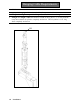
Hanger Assembly Item 1 2 3* 4 5 6* 7* 8 9 10 11 12 13 14 15 16* 17 18 19** 20 21* 22 23 24 25 26 27 Part # Part Name 061-20230 999-806622 Swivel Hex Bolt 999-806594 500 Flex Lock Nut 061-H20 Raise/Lower Cylinder 999-806540 Hex Bolt 999-806532 Flex Lock Nut 999-806503 Flex Lock Nut 002-13143 Suspension Ring 002-13179-2 Lateral Tilt Screw 999-806510 Hex Bolt 999-805842 Hex Bolt 061-91074A029 Lock Washer Set 061-20180 Torque Gage Mount 061-J25 Torque Gage 999-806511 Hex Bolt 999-806503 Flex Lock Nut 999-98
Reducer Assembly 30reduce 11/95 134 Drawings
Reducer Assembly Item 1 2* 3 4* 5* 6* 7 8 9 10 11 12 13 14* 15 16 17 18 19 20 21 22 23 24 25 26 27 28 29 30 Part # 031-R01 031-R02 031-R03 031-R04 031-R05 031-R06 031-24707 031-R08 031-R09 031-R10 031-R11 031-R12 031-R13 031-R14 031-R15 031-R16 031-R17 031-R18 031-R19 031-R20 031-R21 031-R22 031-R23 031-R24 031-R25 031-R26 031-R27 031-R28 031-R29 031-R30 Quantity Per Unit Part Name Cap Screw Shaft Seal Seal Carrier Back-up Ring Quad Ring "O" Ring Output Shaft Thrust Washer Retainer Ring Cone Cup Bearing
Spinner Drive Motor Assembly 30dmotor 4/95 136 Drawings
Spinner Drive Motor Assembly Item 1 2 3* 4* 5 6 7 8 9 10 11 12 13** 14** 15** 16* 17* 18** 19** 20* 21 Part # 031-M01 031-M02 031-M03 031-M04 031-M05 031-M06 031-M07 031-M08 031-M09 031-M10 031-M11 031-M12 031-M13 031-M14 031-M15 031-M16 031-M17 031-M18 031-M19 031-M20 031-M21 Part Name Special Bolts End Cover Seal Ring-Commutator Seal Ring Commutator Assembly Commutator Assembly Manifold Rotor Set Wear Plate Drive Link Thrust Bearing Coupling Shaft Inner Bearing Thrust Washer Thrust Bearing Inner Seal Ba
Spinner Directional Valve Assembly 138 Drawings
Spinner Directional Valve Assembly Item Part # 1 2* 3 4 5 6 7 8* 9 10 061-DV1 061-DV2 061-DV3 061-DV4 061-DV5 061-DV6 061-DV7 061-DV8 061-DV9 061-DV10 Acorn Nut Aluminum Washer Adjust Screw Spring Adaptor Steel Ball Load Check Plug "O"Ring Seal Load Check Spring Load Check Poppet Quantity Per Unit 1 1 1 5 1 1 1 1 1 1 13* 14* 15 16 17 18 19 20 21 22 23 24 24 26 061-DV13 061-DV14 061-DV15 061-DV16 061-DV17 061-DV18 061-DV19 061-DV20 061-DV21 061-DV22 061-DV23 061-DV24 061-DV25 061-DV26 U-Cup Seal "O"R