
Manual
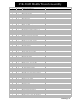
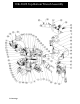
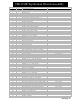
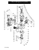

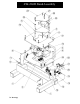
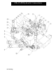

65K-2GJR Stand Assembly
77
Drawings
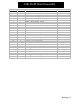
ITEM QTY. PART NO./DESCRIPTION COMMENTS
1 1 30025 Stand W eldment Sub-Assy
2 1 30099 Valve Housing Btm Assy
3 3 30103-624 Valve Cover Spacer
4 1 30100 Valve Housing, Top
5 3 30103-350 Valve Cover Spacer
6 1 30098 Hose Cover
7 1 30059-1 Right Guard, Stand
8 1 30059-2 Left Guard, Stand
9 4 806246_1.2-13 x 1.00 Hex Bolt Grd. 9
10 4 810648_3.8 Flat W asher
11 19 806012 3.8-16 X 1.0 Lg Hex Bolt
12 4 91074A036 Lock W asher Assembly, 3.4
13 3 806538_3.4-16 x 2.00 lg.D Hex Bolt Grd. 9
14 1 806541D_3.4-16 x 4.00 Lg. Hex Bolt Grd. 9
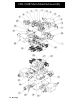
15 1 65K-2GJR Main Manifold Assembly See Explosion
16 4 806004_3.8-16 x .75 Lg. Hex Bolt
17 24 810645_3.8 Lock W asher
18 4 810703_1.2 Lock W asher
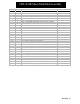
19 1 65K-2GJR Air Pilot Assy See Explosion
20 1 65K-2GJR Oiler Block Assy See Explosion
21 2 810616_5.16 Lock W asher
22 2 805922_5.16-18 x 2.0 Hex Bolt
23 1 30098-1 Open_Closed Center Manifold Plate Optional
24 3 30103-231 Spacer
25 1 65K-2GJR Open_Closed Center Manifold Optional
26 4 806051_3.8-16 x 3.50lg. Hex Bolt
27 2 806025_3.8-16 x 1.50 lg. Hex Bolt