
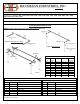
Product Manual

Rev. 10.09.13 aj Page 3 of 4 ©2013 HAUSMANN INDUSTRIES, INC.
Tools Required:
Allen Wrench (Included)
A) INSTALLATION INSTRUCTIONS (S320, S321, 1300, 1386, 1387, 1390, 1391, 1392 & 1393)
To install the parallel bars clear a space big enough to move around with ease.
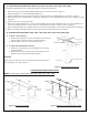
1. Place Uprights on Platform Base as shown in Figure 6.
2. Secure Uprights to Platform Base using 5/16” x 1 ½” Bolts and Lock Washers (included).
NOTE: Use innermost four holes to mount for Model # 1300 and outermost four holes for Model # S320, S321, 1390,
1391, 1392 and 1393 as shown in Figure 7.
3. Install locking pin in 4
th
hole of Adjustable height post.
4. Only for Model #1300 , Slide the two ‘T’ fittings on each bar and then place them onto the Adjustable height post in the
uprights and go to step 9.
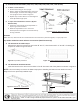
5. Slide on two (or three for Models 1386 & 1387 only) Adjustable arms on one bar as shown in Figure 1 page 1.
6. Once the adjustable arms are in place slide the arms with the bar into the adjustable ‘T’ as shown in Figure 5.
7. When the arms are in the adjustable ‘T’ attach the adjustable ‘T’ to the adjustable height post in the upright as shown
in Figure 5.
8. Repeat steps 1 thru 3 for the other bar.
9. After completing all steps, tighten all the set screws to secure the bars in place with the Allen wrench provided.
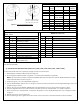
Product Specifications
Model #
Bar
Length
Height
Width
Weight
Capacity
S320
10’
28”-41”
15" - 28"
350 lbs
S321
7’
28”-41”
15" - 28"
350 lbs
1300
10’
28”-41”
26”
400 lbs
1384
10’
29”-42”
20”-32” (Child)
15" - 28"
400 lbs
1386
10’
29”-42”
22" - 35"
600 lbs
1387
7’
29”-42”
22" - 35"
600 lbs
1390
10’
29”-42”
15" - 28"
400 lbs
1391
7’
29”-42”
15" - 28"
400 lbs
1392
12’
29”-42”
15" - 28"
400 lbs
1393
10’
29”-42”
15" - 28"
400 lbs
PARTS LIST
Model # S320,S321,1300,1384, 1390, 1391,
1392, 1393
Model # 1386,1387
PART
QUANTITY
DESCRIPTION
PART
QUANTITY
DESCRIPTION
A
4
Adjustable "T"
A
6
Adjustable "T"
B
2
4
Bar (see chart above for length)
Bar (Only for 1384)
B
2
Bar (see chart above for length)
C
4
Upright
C
6
Upright
D
4
Locking Pin
D
6
Locking Pin
E
4
Adjustable Height Post
E
6
Adjustable Height Post
F
4
Adjustable Arm (N/A for 1300)
F
6
Adjustable Arm
G
1
Platform Base
G
1
Platform Base
H
16
5/16” x 1 ½” Bolt W/ Lock Washer
H
24
5/16” x 1 ½” Bolt W/ Lock Washer
I
4
Control Knobs (N/A for 1300)
I
6
Control Knobs
J
11
Ladder Steps (1393 only)
K
1
Balance Beam 89 ¾”L x 6”W x 3
3/8”H (1393 only)
Innermost 4 holes for
Model #1300
Outermost 4 holes for Model #
S320, S321, 1300, 1384, 1386,
1387, 1390, 1391, 1392, 1393
Figure 7: Inner and Outermost holes