Translation of the ORIGINAL INSTRUCTION BOOK 2G40 2G40 H 0000 433 302 06 - ENG - 01.11 - 0.
A new HATZ Diesel engine - working for you This engine is intended only for the purpose determined and tested by the manufacturer of the equipment in which it is installed. Using it in any other manner contravenes the intended purpose. For danger and damage due to this, Motorenfabrik HATZ assumes no liability. The risk is with the user only. Use of this engine in the intended manner presupposes compliance with the maintenance and repair instructions laid down for it. Noncompliance leads to engine breakdown.
Contents Page Page 1. Important notes on safe operation of the engine 3 5.3. 2. Description of the engine 5 3. 3.1. 3.2. 3.3 3.4. 3.5. General information Technical data Transport Instructions for installation Load on engine Type plate 6 6 7 7 7 8 4. Operation 4.1. Before initial start-up 4.1.1. Engine oil 4.1.2. Oilbath air cleaner 4.1.3. Fuel 4.2. Starting the engine 4.2.1. Preparations for starting 4.2.2. Electric starter 4.3. Stopping the engine 8 8 8 9 10 11 11 11 13 5. 5.1.
1. Important notes on safe operation of the engine HATZ diesel engines are economical, stronly built and long-lasting. They are therefore frequently chosen for commercially and industrially operated equipment and machinery. Since the engine forms part of the finished equipment or machine, its manufacturer will take all the applicable safety regulations into account. Nevertheless, we give below certain additional comments on operating safety, and would recommend you to note them carefully.
Important notes on safe operation of the engine – Stop the engine before performing any maintenance, cleaning- or repair work. – Stop the engine before refuelling. Never add fuel near a naked flame or a source of sparks. Don't smoke. Don't spill fuel. – Keep explosive materials as well as flammable materials away from the engine because the exhaust gets very hot during operation. – Wear close-fitting clothing when working on a running engine.
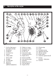
2. Description of the engine Fig.
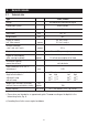
3. General remarks 3.1. Technical data Type 2G40 / 2G40H Design Air-cooled four-stroke diesel engine Combustion system Direct injection Number of cylinders 2 Bore/stroke mm 92 / 75 Displacement cm³ 997 Engine oil content incl. filter renewal l. approx. 2.5 excl. sump 1) 3.0 incl. sump 1) Difference between „max“ and „min“ levels l. approx. 0.8 1) Engine oil pressure Engine oil consumption (after running-in period) min. 1 bar at 900 r.p.m. engine speed approx.
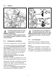
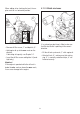
3.2. Transport 2 3 The lifting eyebolt provided as standard equipment is intended for safe movement of the engine. It is not intended for lifting complete machinery to which the engine is attached, and this is strictly forbidden. The permitted loads and elements on the speed adjusting lever and the stop lever should be observed as an exess can lead to damage to the contacts and inner governor parts. 3.4. 3.3.
3.5. ➀ Type plate 4. Operation 4.1. Before initial start-up Engines are normally delivered without fuel and oil. ➁ ➂ 4.1.1. Engine oil ➃ Oil quality Qualified are all trademark oils which fulfil at least one of the following specifications: ACEA – B2 / E2 or more significant API – CD / CE / CF / CF-4 / CG-4 or more significant. 4 If engine oil of a poorer quality is used, reduce oil change intervals to 150 hours of operation. The type plate is placed on the air guide (Fig. 1, pos.
When adding oil or checking the level, the engine must be in a horizontal position. 1 4.1.2. Oilbath air cleaner 2 7 6 If a cyclone-type dust trap is fitted, make sure that the dust outlet is pointing in the correct direction. – Remove oil filler screw „1“ and dipstick „2“. – Add engine oil up to the max. mark on the dipstick. Lubricating oil capacity: see Chapter 3.1. – Fill the oil tank up to mark „1“ with engine oil.
4.1.3. Fuel 9 Before starting for the first time or if the fuel system was run dry, prime it by operating lever „1“ on feed pump „2“ until fuel is heard to flow back into the fuel tank through the return line. 8 Stop the engine before refuelling. Never add fuel near a naked flame or a source of sparks. Don't smoke. Use only pure fuel and clean filling equipment. Take care not to spill fuel. At temperatures below 0 °C, winter-grade fuel should be used or paraffin added to the fuel well in advance.
4.2. Starting the engine Do not run the engine in closed or badly ventilated rooms – danger of poisoning! Before starting the engine, make sure that no one is within the danger area near the engine or the machinery it is driving, and that all the necessary guards are installed. 4.2.1. Preparations for starting – If possible, disengage the engine from any driven equipment The auxiliary equipment should always be placed in neutral. 11 Never use starting aids in the form of aerosols or sprays ! 4.2.2.
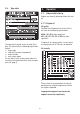
– As soon as the engine runs, release the start key. It must return to position I by itself and remain in this position during operation. The battery charge telltale and oil pressure warning must go out immediately after starting. Indicator light „1“ is on when the engine is in operation. Preheating device with automatic heating timer (additional equipment) The preheating light „6“ lights up additionally at temperatures below 0° Celsius (Fig. 12).
4.3. Stopping the engine Stop Start Run 2 Start 3 Stop 13 14 – Move speed control lever „1“ back to the „STOP“ position. – The battery charge telltale light „2“ and the oil pressure warning light „3“ come on. – On engines with the lower idling speed out of use, move speed control lever „1“ back, then move stop lever „2“ towards STOP and hold it there until the engine has come to a standstill. – Turn the starter key back to position „0“ and pull it out.
5. Maintenance The engine must be stopped before any maintenace work is attempted. Comply with legal requirements when handling and disposing of old oil, filters and cleaning materials. Keep the engine's starting key and starting handle out of reach of unauthorized persons. To immobilize engines with an electric starter, disconnect the negative battery terminal. At the end of the maintnance work, check that all tools have been removed from the engine and all safety guards, covers etc.
The above maintenance chart is supplied with every engine. This label should be affixed to the engine or equipment in an easily visible position. The maintenance chart governs the maintenance intervals. For new or reconditioned engines, the following must always be carried out after the first 25 operating hours. – Replace engine oil and oil filter, chap. 5.3.2. – Check tappet clearance, and adjust if necessary, chap. 5.3.3. – Examine screw connections, chap. 5.3.5.
5.2. Maintenance work every 8 operating hours – 15 With oilbath air cleaner: 5.2.1. Check engine oil level When the oil level is checked, the engine must be stopped and in a horizontal position. – Remove any dirt in the dipstick area. 1 2 16 – Inspect air inlets „1“ (depending on version) for severe dirt and dust deposits, and clean if necessary. – Make sure that dust outlet „2“ on the cyclone-type dust trap (depending on version) is not obstructed, and clean if necessary (chap. 5.3.1.).
– Check that connecting hose „3“ and hose clips „4“ are in good condition and not leaking (fig. 17). 5.2.3. Check the cooling air system Heavy contamination is an indication that increased dust accumulation necessitates acorrespondingly shorter maintenance interval. 1 18 19 – Run the engine up to maximum speed briefly and check that indicator lamp „1“ (depending on version) comes on briefly or that the red zone is visible in maintenance indicator „3“.
5.3. Maintenance work every 250 operating hours 5.3.1. Maintenance work on oilbath air cleaner 3 1 2 21 – Detach upper part of air cleaner „1“ from engine and rinse in diesel fuel. – Allow the diesel fuel drip off thoroughly, or wipe it off, before re-assembling. 20 – Install a new filter packing if the sealing surface is uneven, the body of the filter is cracked and/or filter wool is missing. Trap the old oil and dispose of it in accordance with local legislation.
22 24 – Slacken off and unscrew the throwaway engine oil filter using HATZ strap wrench „1“, Order No. 620 307 01, or a similar tool. 2 23 1 – Take out drain plug „1“ and allow the oil to drain out completely (fig. 22 without oil sump, fig. 23 with oil sump). G3/28 25 – Insert oil drain plug „1“ with a new sealing ring „2“ and tighten. – Use a screwdriver to lift mesh screen „1“, which is located behind the filter element, away from the oil pressure relief valve. Do not damage contact face „2“.
– After cleaning, press the mesh screen back on to the oil pressure relief valve. 5.3.3. Check and adjust vlave clearances – Adjust only when the engine is cold (10 - 30 °C). – Remove any dirt from the area where the cover is attached to the cylinder head. 26 – Clean sealing face „1“ thoroughly. – Never re-use the throwaway filter element. Oil sealing ring „2“ on the new filter element lightly. 27 – Remove screws „1“ and take off cover „3“ complete with sealing rings „2“ and „4“.
Adjusting: If dirt deposits are damp or oily: – Disconnect the battery. – Measure valve clearance with 0.10 mm feeler gauge „5“ (fig. 27, chapt. 3.1.). – Apply a detergent solution (cold cleaner or similar) to the entire system in accordance with the manufacturer's instructions, then spray off with a powerful water jet. Do not splash electrical device with water jet or pressure jet during engine cleaning.
5.3.5. Check threaded connections 5.4. Check the condition and tightness of all threaded connections, pipes and lines, hose clips and other fastenings on the engine or its mountings which can be reached during maintenance work. Do not tighten the cylinder head bolts. Maintenance work every 500 hours of operation 5.4.1. Renew the fuel filter The maintenance intervals for the fuel filter are dependent upon the purity of the diesel oil being used and, if necessary, may have to be reduced to 250 hours.
5.4.2. Dry-type air cleaner maintenance Cleaning the filter cartridge It is best to clean the filter cartridge only when the maintenance indicator displays the appropriate signal. This is only the case if the maintenance indicator functions properly (chap. 6.1.). Apart from this, the cartridge should be renewed after 500 hours of operation.
6. 6.1. – Create a vacuum at the maintenance switch with powerful suction, indicator lamp „1“ must light up (fig. 33). Functional test Air filter maintenance indicators (only on version with Dry-type air cleaner) – If there is no reaction, check cable connectors and replace filament lamp and/or maintenance switch if necessary. For electrical indicator For mechanical indicator – Unscrew maintenance indicator „3“ (fig. 33).
7. Malfunctions – causes and remedies Malfunctions Possible causes Remedy Chap. The engine does not start or not immediately, can however be turned over with the starter motor. Speed adjustment lever in the stop or idle position. Stop lever in stop position. Move the lever in START position. 4.2.1. No fuel at the fuel-injection pump. Fill up with fuel. 4.1.3. Check the complete fuel supply system systematically. If no result, check: - fuel supply line to the engine. - fuel filter.
Malfunctions Possible causes Remedy Chap. At low temperatures. Starting speed too low: - Oil too viscous. Replace and fill up with oil. 5.3.2. 4.1.1. Check the battery, if necessary contact a service station. 8. Check the electical system and its components or contact HATZ service station ! 8. Speed control lever not located far enough in the start direction. Move the lever to START position. 4.2.1. Device not disengaged. Disengage the engine from the device if possible.
Malfunctions Possible causes Engine shuts down independently during operation. Fuel supply interrupted: - Tank run dry - Fuel filter blocked. - Fuel feed pump defective. Mechanical malfunctions. In addition, if automatic electrical engine shutdown is installed. Drop off in performance and speed of the engine. Stop signal from monitoring element because of: - oil pressure too low. - cylinder head temperature too high. Remedy Chap. Fill up with fuel. Replace fuel filter.
Malfunctions Possible causes Remedy Chap. Drop off in engine performance and speed, black smoke from the exhaust. Air filter contaminated. Clean air filter. Incorrect valve clearances. Adjust valve clearances. 5.3.1. 5.4.2. 5.3.3. Injector jets unserviceable. See workshop manual. Engine runs very hot, the indicator lamp for cylinder head temperatur (additional equipment) comes on. Too much oil in the engine. Drain off oil to the upper mark on the dipstick. 5.3.2.
8. – When carrying out welding work on the engine or attached equipment, attach the earth (ground) clip as near as possible to the welding point, and disconnect the battery. If an alternator is fitted, separate the plug connector leading to the voltage regulator. Work on the electrical system Batteries generate explosive gases. Keep them away from naked flame and sparks which could cause them to ignite. Do not smoke. Protect eyes, skin and cloth against the corrosive battery acid.
30
CALIFORNIA Proposition 65 Warning Diesel engine exhaust and some of its constituents are known to the State of California to cause cancer, birth defects, and other reproductive harm.