
User guide


Physical Connections
35
IND100133-56
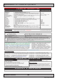
Module Expansion Matrix
Table below indicates how many duplicates of the same module can be installed at the same time. Due to limited
number of internal connectors, different upper/lower area size and technical limitations some combinations (with
duplicates) are naturally not possible to achieve.
Colored Table Cell refers to the “Upper Row” and “Lower Row” tables above from previous page.
COM NMEA COM CAN DIO LAN
A B C D E
2 4 1 1 2
Factory Standards
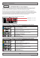
The following illustration indicate mounting locations of the varirty of modules available and how they are numbered to
keep a persistent conguration. This is seen from user’s Point-of-View at rear of the computer unit.
Priority Upper Row Priority Lower Row
CAN [C] COM [A]
NMEA COM [B] NMEA COM [B]
DIO [D] DIO [D]
LAN [E] LAN [E]
Priority numbering starts from Upper Row going to right, then Lower Row going to right as illustrated:
1 2
3 4
Table below indicates how many combinations of modules is possible to install (each table row totals upto max 4).
Further, as per. factory standards, the unique location and shifting of modules are illustrated in the last column, where
the number inside the 2x2 table indicate unique id, starting from 1 to max 4 modules.
COM NMEA COM CAN DIO LAN
Default Factory Mounting Position
(upper row / lower row)
A B C D E
2
1 2
1
1
2
1 2
3
1 2
3
4
1 2
3 4
1
1
2
1 2
1
1
1
1
1 1
1
1