
User guide


17
General Installation Recommendations
Installation
IND100210-20
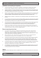
Conguring Housing / Terminal Block connectors
Below is a brief illustration that might be useful during conguration and installation of such connectors. You will need
suitable pre-congured cable(s) and tools to congure the connector(s) and cable(s) that are present in your
installation environment. Below is a sample procedure for a 2-pin DC power connector. The procedure is the same for
other connectors of this type as listed in table above. Unit used as illustration below is for reference only.
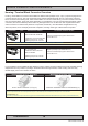
FIG 3
FIG 1
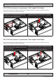
FIG 2
FIG 4
FIG 1: Unscrew (from top) or make sure that the screw terminal (square area) are fully open, so you can secure the
inserted cables correctly to the loose housing connector (it may already be plugged into the unit as per factory
installation).
FIG 2: Insert cables* (from front) and screw / secure the cables by turning the screw on top of the housing to secure
the cables properly. Check that the cables is rmly in place and do not appear loose or falls out when pulling gently.
*Note: Required polarization verication (for instance -/+ for DC power input) should conform with the markings on
the connector area of the unit. Ignoring the markings on the unit or its add-on modules might damage the unit and/or
external equipment in which end, warranty will be void.
FIG 3: Plug the housing into the appropriate connector area of the unit (glass should be facing down) and check again
that the cables secured conforms with the markings on the connector area of the unit. Finalize the installation by
fasten the screws located in front on each side of the housing connector (FIG 4).