USER MANUAL Standard Models Entry Level Models HT C02 - Compact Computer Standard Models: HT C02Hx STC-yzz-wzzz Entry Level Models: HT C02HI STC-yzz-wzzz where x=CPU type, y=OS, w=Power Input (AC or DC*), z=configuration *DC models pending Q2/2015 User Manual HT C02 Updated: 04 Jun 2015 Doc Id: INB10042-4 (Rev 04) Created: 363 Approved: 6987 Please visit www.hatteland-display.com for the latest electronic version of this manual.
Copyright © 2015 Hatteland Display AS Stokkastrandvegen 87B, N-5578 Nedre Vats, Norway. All rights are reserved by Hatteland Display AS. This information may not, in whole or in part, be copied, photocopied, reproduced, translated or reduced to any electronic medium or machinereadable form without the prior written consent of Hatteland Display AS. Review also: www.hatteland-display.com/pdf/misc/doc100703-1_permission_to_create_user_manuals.
Contents Contents..................................................................................... 3 Contents of package........................................................................................... 5 General....................................................................................... 7 About this manual............................................................................................... 8 About Hatteland Display..........................................................
Contents Specifications Factory Options............................................. 43 Specifications - COM Module RS-232.............................................................. 44 PCA100294-1.............................................................................................. 44 Specifications - NMEA / IEC COM Module RS-422 / RS-485.......................... 45 PCA100293-1..............................................................................................
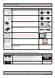
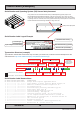
Contents of package Note: Entries listed below are for Standard factory shipments. Customized factory shipments may deviate from this list. Item Description 1 pcs of power cable European Type F “Schuko” to IEC. Length 1.8m Illustration EUR TYPE F IEC Note: Only applicable for factory delivered units with AC Power Input TP52/TC11-1.8M 1 pcs of power cable US Type B plug to IEC. Length 1.8m US TYPE B IEC Note: Only applicable for factory delivered units with AC Power Input TP11/TC11-1.
This page left intentionally blank 6
General 7
Hatteland Display AS About this manual The manual contains electrical, mechanical and input/output signal specifications. All specifications in this manual, due to manufacturing, new revisions and approvals, are subject to change without notice. However, the last update and revision of this manual are shown both on the frontpage and also in the “Revision History” chapter at the end of the manual.
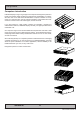
Computers Computers introduction Hatteland Display’s range of type-approved computers is designed to perform in harsh environments while providing the performance and flexibility you expect. We offer rack mount and black box/standalone computer solutions for every need. Our computers are used by system integrators, boat builders and endusers and can be found on all vessel types, all over the world.
Product Labels (Examples) Serial Number and Operating System (OS) license label placement Only present if the unit was delivered with factory installed Operating System (OS) such as Microsoft® Windows® Embedded Enterprise. Label size is 7cm wide x 2.8cm high. The same Product Key is also printed on the “Product Declaration” sheet that follows the unit, check contents of package.
Product Labels (Examples) Quality Control (QC) Label This label indicates that the unit is produced, tested and packed according to manufacturer’s QA specifications. It will include a Personal ID and signature by the personnell responsible for approving the unit in production, test and warehouse departments. Label size is 3cm wide x 2.3cm high.
This page left intentionally blank 12
Installation 13
General Installation Recommendations Installation and mounting of computers 1. Units may be intended for various methods of installation or mounting (rack mounting, panel mounting, bracket mounting, ceiling/wall mounting); for details, please see the relevant mechanical drawings. 2. Adequate ventilation is a necessary prerequisite for the life of the unit. The air inlet and outlet openings must definitely be kept clear; coverings which restrict ventilation are not permissible.
General Installation Recommendations CAUTION This unit contains electrostatic sensitive devices. Observe precautions for handling. Computer Upgrade Precaution Note Users who needs to open the computer to change PCI cards, install more memory, or set internal jumpers can do so without voiding the warranty. Before opening a unit’s housing to remove or touch a board, proper ESD measurements must be taken! 1. Operator should ground himself by using a wrist band. 2.
General Installation Recommendations Housing / Terminal Block Connector Overview Housing / Terminal Block connectors are available in different sizes (example 2-pin, 4-pin, 5-pin) which plugs into the connector area of the unit. They are mounted by factory default and delivered with the unit. The housing / terminal block connectors have steering rails, which ensures that it can not be mounted wrong. The color of these connectors may vary between black, green and orange depending on manufacturer.
General Installation Recommendations Configuring Housing / Terminal Block connectors Below is a brief illustration that might be useful during configuration and installation of such connectors. You will need suitable pre-configured cable(s) and tools to configure the connector(s) and cable(s) that are present in your installation environment. Below is a sample procedure for a 2-pin DC power connector. The procedure is the same for other connectors of this type as listed in table above.
General Installation Recommendations Cabinet cover removal Note: Areas of interest are marked in this section with arrows in RED color. Please disconnect ALL cables from the computer unit before proceeding! 1: Unscrew 3 screws from top of cabinet. Use a Pozidriv #2 screwdriver. 2: Unscrew 3 thumb screws in rear of cabinet. Turn anticlockwise using your fingers or flat screwdriver (if tight). 3: Push cover gently down while pushing forward approx 4: Lift the cover up with both hands. 10mm [0.
General Installation Recommendations PCI / PCIe Card removal / replacement - Introduction Note: Areas of interest are marked in this section with circles and arrows in RED color. Please disconnect ALL cables from the computer unit before proceeding! 1: Unscrew 2 screws on each side of the bracket. Use a Pozidriv #2 screwdriver. 2: Push each side of the bracket, one forward and one backwards in a 45 degree rotation clockwise to slide it out of the tracks. Then lift up the the bracket to remove it.
General Installation Recommendations PCI / PCIe Card removal / replacement - Half Lenght & Full Height Note: Areas of interest are marked in this section with circles and arrows in RED color. Please disconnect ALL cables from the computer unit before proceeding! 1: Place the PCI / PCIe Half Length bracket as shown and push/slide it in so it reaches the end of the card and click in place at the end of the card. 2: Mount 2 screws on top to fasten the PCI / PCIe Half Length bracket securely.
General Installation Recommendations Internal Hard Drive (HDD) removal / replacement (Entry Level Models only) Note: Areas of interest are marked in this section with circles and arrows in RED color. Please disconnect ALL cables from the computer unit and HDD’s before proceeding! 1: Unscrew 4 screws on each side of the PCI bracket. Use a Pozidriv #2 screwdriver. 2: Push each side of the bracket, one forward and one backwards in a 45 degree rotation clockwise to slide it out of the tracks.
General Installation Recommendations DVD/CD Drive removal / replacement (Standard Models only) Note: Areas of interest are marked in this section with circles and arrows in RED color. Please disconnect ALL cables from the computer unit and DVD/CD drive before proceeding! 1: Unscrew 1 thumb screw on the DVD/CD bracket. Turn anti-clockwise using your fingers. 2: Gently pull out the DVD/CD bracket away. Remember it’s orientation and placement. 3: Shift DVD/CD Drive a bit to the side.
General Installation Recommendations Air Filter removal / replacement (M153S30Q20-ACC0015) - Alternative #1 Note: Areas of interest are marked in this section with circles and arrows in RED color. Please disconnect ALL cables from the computer unit and cards before proceeding! 1: Unscrew 4 screws from the fan/filter cover in front of the unit. Use a Pozidriv #2 screwdriver. 2: Gently pull out the fan/filter cover. 3: Gently pull out the Air Filter from the Air Filter Bracket. Either clean or replace it.
General Installation Recommendations Air Filter removal / replacement (M153S30Q20-ACC0015) - Alternative #2 Note: Areas of interest are marked in this section with circles and arrows in RED color. Please disconnect ALL cables from the computer unit and cards before proceeding! 1: Remove cabinet cover (see beginning of this chapter). When cabinet cover is off, unscrew 1 screw 2: Gently pull/slide out the Air Filter Bracket as indicated. on top which keeps the Air Filter Bracket in place.
General Installation Recommendations Front Fan removal / replacement Note: Areas of interest are marked in this section with circles and arrows in RED color. Please disconnect ALL cables from the computer unit before proceeding! 1: Remove cabinet cover (see beginning of this chapter) Then unscrew 4 screws from the fan/filter cover in 2: Gently pull out the fan/filter cover. front of the unit. Use a Pozidriv #2 screwdriver. 3: Unscrew 1 screw on top that keeps the Air Filter Bracket in place.
General Installation Recommendations Mounting Brackets for Console Mounting - HT 00226 OPT-A1 Note: The unit comes with mounting brackets and screws for console mounting in the package. Please review specifications and “Technical Drawings - Accessories” chapter in this user manual for additional information. Bracket View and Measurements 1: Bottom view showing 4 mounting holes. Connector Side 2: Mount the brackets with 4 x M6x8 (included).
General Installation Recommendations 19 inch Rack Kit 4U - HT 00223 OPT-A1 Note: The unit can also be mounted inside a Hatteland Display 4U cabinet for rack mounting purposes. Please review specifications and “Technical Drawings - Accessories” chapter in this user manual for additional information. 1: Empty 4U cabinet suitable for the computer and final solution (note that there is no 4U top cover, as the HT C02 model has its own already). 2: Showing mounting and screw (included) positions.
Physical Connections Front area of computer models 12cm FAN intake+filter Standard SSD/HDD Power LED Entry SSD/HDD Activity LED USB2.0 Power LED Power Button DVD/CD-RW Reset Button USB2.0 2.5” Removable SSD/HDD Trays. Device Order: #3 (at top), #2, #1 and #0 at bottom Power Button Power LED Reset Button AIR FILTER: The computer unit features an cleanable / replaceable air filter located in front behind the metal hatch.
Physical Connections 4 x 2.5” Removable SATA SSD/HDD Trays (only Standard model): The unit can utilize 4 x Storage Devices (SSD/HDD), 2.5” size. (1 x tray is by factory default occupied, Device #0). The storage devices can be easily be upgraded or replaced by pulling the SSD/HDD tray out.
Physical Connections Connector area of computer - Standard and Entry Level Models Expansion / Module Area Power Input AC Power Input DC PCIe x16 PCIe x4 PCI PCIe x1 Expansion Area for 4 x PCI Brackets Grounding Screw RS-485/422 COM2 DVI-D USB2.0 Network Realtek Network Intel GBLAN USB GBLAN #2 / #1 USB3.0 i210 (top) RS-232 COM1 DisplayPort DVI-I 2.0/1.
Physical Connections 1+1 x COM Serial Port INPUT/OUTPUT: Supports RS-232 (COM1) or RS-485/422 (COM2) using D-SUB 9P Male on-board connectors. Fasten the cable to the connector using the provided screws on the cable housing itself. For configuration, please review the Appendix chapter, section “BIOS - On-board COM Ports Configuration”. 1 x DisplayPort (DP) OUTPUT: Connect your DP (male) cable to the DisplayPort (v1.2) 20P connector (female) on the rear side of the unit.
Physical Connections 3 x PCIe + 1 x PCI Slots: Supports Full Height and Full Length Profile cards. Cards is normally installed from factory. Please review the General Installation Recommendations chapter in this manual for more information. Additionally consult the 3rd party manual available on the attached documentation CD delivered with this unit.
Physical Connections Added functionality through 4 x PCI Sized Metal Brackets If the PCI slots are not all occupied by regular internal PCI Based Cards (as indicated on previous page), the PCI Sized Holes can be fitted with additional functionality which are connected to the main board offering more connectors mounted on PCI Metal Brackets. Example illustration showing 4 x PCI Metal Bracket options (1 x AMP, 1 x PS/2, 1 x USB2.0+USB3.
Physical Connections 4 x EXPANSION AREA for Optional Modules: The HT C02 computers supports a multitude of combinations and gives additional features to the unit by taking advantage of the 4 available expansion areas. The table below lists all modules currently available for factory mounting - including combinations and duplicates of each module possible (see next page).
Physical Connections Module Expansion Matrix Table below indicates how many duplicates of the same module can be installed at the same time. Due to limited number of internal connectors, different upper/lower area size and technical limitations some combinations (with duplicates) are naturally not possible to achieve. Colored Table Cell refers to the “Upper Row” and “Lower Row” tables above from previous page.
Physical Connections COM NMEA COM CAN DIO LAN A B C D E 1 Default Factory Mounting Position (upper row / lower row) 1 1 1 1 1 1 1 1 1 1 1 1 1 1 1 1 1 1 2 1 2 1 2 1 3 1 1 2 1 1 1 1 1 1 1 1 1 1 1 1 2 1 1 2 1 1 1 1 2 1 1 2 3 1 1 1 1 1 1 2 1 1 2 1 1 2 1 1 2 1 1 1 2 1 1 1 2 1 1 2 2 1 1 1 1 2 1 1 3 2 1 1 2 1 3 1 1 2 1 1 2 1 1 1 1 1 1 1 2 1 2 1 2 1 2 1 2 1 2 2 2 1 1 1 3 3 1 2 2 1 1 36 IND100133-56
Physical Connections COM NMEA COM CAN DIO LAN A B C D E 2 1 2 1 2 1 2 1 1 2 1 1 1 1 2 1 1 1 2 1 1 1 2 1 1 1 1 1 1 1 1 1 1 1 1 1 1 1 1 1 1 1 1 1 1 1 1 1 1 1 1 1 1 1 1 1 Default Factory Mounting Position (upper row / lower row) 1 1 1 1 1 1 1 1 1 1 1 1 1 1 1 1 1 1 37 IND100133-56
Physical Connections Factory Preset COM Port Numbering Hatteland Display offer a wealth of options resulting in many Operating System numbered COM ports. The table below lists all known ports that are assigned if a specific factory option (or duplicates of them) were factory mounted prior to manufacturing and delivery of units to customer. Internal on-board, PCI based cards and Modules are listed. The numbering are only applicable for COM Ports, and not other ports, such as network RJ-45.
Specifications 39
Specifications - HT C02Hx STC-yzz-wzzz SPECIFICATIONS Note: All specifications are subject to change without prior notice! Please visit www.hatteland-display.com for the latest electronic version. Note: All specifications are subject to change without prior notice! Please visit www.hatteland-display.com for the latest electronic version.
Specifications - HT C02HI STC-yzz-wzzz SPECIFICATIONS Note: All specifications are subject to change without prior notice! Please visit www.hatteland-display.com for the latest electronic version. Note: All specifications are subject to change without prior notice! Please visit www.hatteland-display.com for the latest electronic version.
This page left intentionally blank 42
Specifications Factory Options 43
Specifications - COM Module RS-232 All specifications are subject to change without prior notice! DATA SHEET This information may not, in whole or in part, be copied, photocopied, reproduced, translated or reduced to any electronic medium or machinereadable form without the prior written consent of Hatteland Display AS. The products may not be copied or duplicated in any way.
Specifications - NMEA / IEC COM Module RS-422 / RS-485 DATA SHEET This information may not, in whole or in part, be copied, photocopied, reproduced, translated or reduced to any electronic medium or machinereadable form without the prior written consent of Hatteland Display AS. The products may not be copied or duplicated in any way.
Specifications - NMEA / IEC COM Module RS-422 / RS-485 NMEA RS-422 / RS-485 (ECDIS) module (PCA100293-1): Suitable for communication with serial protocol based equipment. Connect and secure your cables to the Terminal Block 3.81 connector. For more information please review the Data Sheet in the Appendix chapter as well as the “Housing Connector Overview” in this manual. Note: Our units is based on an isolated RS-485 interface with enhancements to meet NMEA standard.
Specifications - CAN Module with CO-Processor All specifications are subject to change without prior notice! DATA SHEET This information may not, in whole or in part, be copied, photocopied, reproduced, translated or reduced to any electronic medium or machinereadable form without the prior written consent of Hatteland Display AS. The products may not be copied or duplicated in any way.
Specifications - Isolated Digital Input/Output Module All specifications are subject to change without prior notice! DATA SHEET This information may not, in whole or in part, be copied, photocopied, reproduced, translated or reduced to any electronic medium or machinereadable form without the prior written consent of Hatteland Display AS. The products may not be copied or duplicated in any way.
Specifications - Isolated Digital Input/Output Module All specifications are subject to change without prior notice! SPECIFICATIONS Additional • Cable connector • Test and certicate Note: All specifications are subject to change without prior notice! Please visit www.hatteland-display.com for the latest electronic version. 4 x Phoenix 1827732 (MC 1,5/ 5-STF-3,81) Terminal Block 3.
Specifications - LAN Module All specifications are subject to change without prior notice! DATA SHEET This information may not, in whole or in part, be copied, photocopied, reproduced, translated or reduced to any electronic medium or machinereadable form without the prior written consent of Hatteland Display AS. The products may not be copied or duplicated in any way.
Specifications Accessories 51
Specifications - External Modules (USB) All specifications are subject to change without prior notice! DATA SHEET This information may not, in whole or in part, be copied, photocopied, reproduced, translated or reduced to any electronic medium or machinereadable form without the prior written consent of Hatteland Display AS. The products may not be copied or duplicated in any way.
Specifications - External Modules (USB) All specifications are subject to change without prior notice! SPECIFICATIONS Note: All specifications are subject to change without prior notice! Please visit www.hatteland-display.com for the latest electronic version. Ordering Details: TypeNumber Description Internal Specications (link to separate datasheets) HT 00262 OPT-A1 NMEA COM 4 x NMEA RS-422/RS-485 isolated Via 5-pin Terminal Block 3.
This page left intentionally blank 54
Technical Drawings 55
This document is the property of Hatteland Display AS. This document and any authorized reproduction thereof, must not be used in any way against the interest of Hatteland Display AS. Any authorized reproduction, in whole or in part, must include this legend. Hatteland Display Proprietary information. Not to be distributed to any third party without written permission. Dimensions might be shown with or without decimals and indicated as mm [inches]. Tolerance on drawings is +/- 1mm.
Technical Drawings - Accessories 57
This document is the property of Hatteland Display AS. This document and any authorized reproduction thereof, must not be used in any way against the interest of Hatteland Display AS. Any authorized reproduction, in whole or in part, must include this legend. Hatteland Display Proprietary information. Not to be distributed to any third party without written permission. Dimensions might be shown with or without decimals and indicated as mm [inches]. Tolerance on drawings is +/- 1mm.
This document is the property of Hatteland Display AS. This document and any authorized reproduction thereof, must not be used in any way against the interest of Hatteland Display AS. Any authorized reproduction, in whole or in part, must include this legend. Hatteland Display Proprietary information. Not to be distributed to any third party without written permission. Dimensions might be shown with or without decimals and indicated as mm [inches]. Tolerance on drawings is +/- 1mm.
This document is the property of Hatteland Display AS. This document and any authorized reproduction thereof, must not be used in any way against the interest of Hatteland Display AS. Any authorized reproduction, in whole or in part, must include this legend. Hatteland Display Proprietary information. Not to be distributed to any third party without written permission. Dimensions might be shown with or without decimals and indicated as mm [inches]. Tolerance on drawings is +/- 1mm.
This document is the property of Hatteland Display AS. This document and any authorized reproduction thereof, must not be used in any way against the interest of Hatteland Display AS. Any authorized reproduction, in whole or in part, must include this legend. Hatteland Display Proprietary information. Not to be distributed to any third party without written permission. Dimensions might be shown with or without decimals and indicated as mm [inches]. Tolerance on drawings is +/- 1mm.
This page left intentionally blank 62
Appendixes 63
BIOS - On-board COM Ports Configuration Low / High Speed How to configure COM1 and COM2 speed mode in BIOS. In high speed mode, the Baudrate goes above 115200 bps. Due to limitation of generic Operating System (OS) Driver, it is required to set 9600 for achieving 128000 in high speed mode. Before configuring it is assumed the user has the appropriate knowledge on how to enter and navigate within BIOS and change values.
BIOS - COM Ports Configuration 3: Then navigate to "Speed mode" (for the port chosen) and select Low/High Speed based on table below: Aptio Setup Utility - Copyright (C) 2012 American Megatrends, Inc. Advanced Serial Port 1 Configuration Serial Port Device Settings [Enabled] IO=3F8h; IRQ=4; Change Settings Speed Mode [Auto] [Low Speed] Speed Mode Low Speed High Speed Change the speed mode for serial port (Baudrate) : Select Screen : Select Item Enter: Select +/-: Change Opt.
BIOS - COM Ports Configuration COM2 Mode Choose desired COM2 mode from choices: Aptio Setup Utility - Copyright (C) 2012 American Megatrends, Inc. Advanced COM2 mode selection NCT6102D Super IO Configuration NCT6102D Super IO Chip Serial Port 1 Configuration Serial Port 2 Configuration NCT6102D WatchDog Count Mode WatchDog Timeout Value [Second] 0 COM2 Mode COM Auto RTS [Full duplex master...
BIOS - How to create RAID volume Instructions Before configuring it is assumed the user has the appropriate knowledge on how to enter and navigate within BIOS and change values. When BIOS screen has been accessed, follow the steps below. 1: Go to Advanced / SATA Configuration, and click enter: Aptio Setup Utility - Copyright (C) 2012 American Megatrends, Inc.
BIOS - How to create RAID volume During next boot press Ctrl+I to enter RAID Setup when the following menu is displayed: Intel(R) Rapid Storage Technology - Option ROM - 12.5.0.1815 Copyright(C) 2003-13 Intel Corporation. All Rights Reserved. RAID Volumes: None defined. Physical Devices: ID Device Model 2 INTEL SSDSC2BB08 2 INTEL SSDSC2BB08 Press to enter Serial # Size Type/Status(Vol ID) WL402303Y5080KGN 74.5GB Non-RAID Disk WL402303ZS080KGN 74.5GB Non-RAID Disk Configuration Utility.
BIOS - How to create RAID volume Then configure the RAID Volume as you want: Intel(R) Rapid Storage Technology - Option ROM - 12.5.0.1815 Copyright(C) 2003-13 Intel Corporation. All Rights Reserved. [ CREATE VOLUME MENU ] NAME: RAID Level: Disks: Strip Size: Capacity: Sync: Volume1 RAID1(Mirror) Select Disks N/A 74.5 GB N/A Create Volume [ HELP ] Enter a unique volume name that has no special characters and is 16 characters or less.
BIOS - How to create RAID volume Procedure to reset disk mode in Microsoft® Windows® 7 before capturing image: - Open Registry Editor and go to: HKEY_LOCAL_MACHINE\System\CurrentControlSet\Services\ For each of the subkeys: Msahci, iaStorV and iaStor; - Find “Start” string, doubleclick and change value from 3 to 0, if not set. - Exit and shutdown the unit. System image should be saved before Windows is booted again.
SSD Selection Guide Solid State Disk (SSD) Devices Last revised : 4 November 2014 SSD's has many benefits over conventional hard drives, but when it comes to write endurance it is important to choose the technology to be used with care. It is of very high importance to consider several aspects when using an SSD for a particular application, below the most critical ones, such as: - Nature of the application, data written to disk during a defined time period (worst case).
SSD Selection Guide Calculation of required size of SSD (Multi-Level Cell - MLC) device) The table below details the write endurance of the an enterprise environment. All values are verified by Hatteland Display during the qualification / selection process. Write Endurance Specifications Intel® SSD 320 Series Write Endurance Specifications Current 2.
SSD Selection Guide Example (based on Intel® SSD 320 Series) A general assessment based on requirements to determine the most suitable SSD device. When these factors are known or specified in detail, we can calculate and conclude which SSD device is most suitable (see bottom of page). Question Client Answer We need to know how much data is written to disk Chart Data : 2GB /Week (worst case) during a known time period (per second, Log/User Data: : 10kB /Sec minute, hour etc.
SSD Selection Guide Preparation 1: Install "Intel® Solid-Sate Drive Toolbox" at target system. 2: Install the unit in valid configuration, i.e. the application shall running valid use case, if possible use worst case scenario (with respect to disk activity). 3: Before start of measurement, check and store actual SMART data. - Start "Intel® Solid-Sate Drive toolbol". - Refresh (button at home screen). - Export SMART data, store current data at file (button at home screen).
Pinout Assignments Connectors illustrated here are either standard by factory default or may be available (through factory customization). Note that some combinations may not be possible due to space restrictions. List also valid for customized models. All pin out assignments are seen from users Point of View (POV) while looking straight at the connector. Please review the dedicated datasheet or technical drawings for your actual unit to identify and determine the presence of desired connector.
Pinout Assignments 18/24/24+5 pin DVI-D, DVI-I, Single Link, Dual Link Combined Female 1 2 3 4 5 6 7 8 9 10 11 12 13 14 15 16 C1 C2 1 2 3 4 5 6 7 8 C5 17 18 19 20 21 22 23 24 C3 C4 PIN 01 PIN 02 PIN 03 PIN 04 PIN 05 PIN 06 PIN 07 PIN 08 PIN 09 PIN 10 PIN 11 PIN 12 PIN 13 PIN 14 PIN 15 PIN 16 PIN 17 PIN 18 PIN 19 PIN 20 PIN 21 PIN 22 PIN 23 PIN 24 PIN C1 PIN C2 PIN C3 PIN C4 PIN C5 T.M.D.S. Data2 - (Digital - RED link 1) T.M.D.S. Data2 + (Digital + RED link 1) T.M.D.S. Data2/4 Shield T.M.D.S.
Pinout Assignments 10+10 pin Isolated Digital Input/Output Module Type Number “HT00268 OPT-A1” Module A 4+4 pin CAN I/O Module, 2 channels Type Number “HT 00254 OPT-A1” Module B X8 CAN1 1 2 3 4 1 2 3 4 X9 CAN2 Module A A1 A2 B1 B2 O1 C1 C2 D1 D2 O2 Module B External Power + N/C (Not Connected) External Power - (GND1) N/C (Not Connected) HS[0] HS[1] N/C (Not Connected) HS[2] N/C (Not Connected) HS[3] A1 A2 B1 B2 O1 C1 C2 D1 D2 O2 IN+[0] IN-[0] IN+[1] IN-[1] N/C IN+[2] IN-[2] IN+[3] IN-[3] N/C
Trouble-shooting GENERAL TROUBLE-SHOOTING CD-ROM FAILURE OR READ/DETECTION PROBLEMS? If the product are operated/located in a area with extreme condensation, the CD/DVD-ROM drive may not work correctly due to condensation on the read head. Keep the product on for a while until it’s reached normal operating temperature, and retry accessing discs. Otherwise, consider using USB memory sticks or alternative storage devices.
Declaration of Conformity We, manufacturer, Hatteland Display AS, Stokkastrandvegen 87B, N-5578 Nedre Vats, Norway declare under our sole responsibility that the JH MMD, JH MMC, JH STD, JH MIL, HM NMD, HM MIL, HM CMD, HT STD, HD MMD, HM MMD, HT MMC, HD MMC and HT/HM (computers) product ranges is in conformity with the following standards in accordance with the EMC Directive.
Return Of Goods Information Return of goods: (Applies not to warranty/normal service/repair of products) Hatteland Display referenced as “manufacturer” in this document. Before returning goods, please contact your system supplier before sending anything directly to manufacturer. When you return products after loan, test, evaulation or products subject for credit, you must ensure that all accessories received from our warehouse is returned.
General Terms and Conditions As of January 2015, Hatteland Display AS’ “Terms of Sales and Delivery” and “Warranty Terms” has been substituted by the updated ”General terms and conditions for sale of goods and performance of additional services” (the “General Terms and Conditions”).
Signal Output Combinations Overview of tested signal outputs The latest computers from Hatteland Display are capable of displaying 3 signals simultaneously via DVI-D, DVI-I or RGB/VGA (via adapter) or through the DisplayPort (DP) (including DP to DVI adapter) connectors. Below, the list of possible combinations the hardware support. All resolutions and frequencies are indicated as max. Everything lower than max can be used, even as low as 640x480 (VGA) for all 3 signal outputs.
Notes General Notes: - License Terms for the installed OEM Operating System (OS) can be found in the following default factory paths: Note: This is a general listing for a varity of OS’s Hatteland Display can factory install depending on unit. Please check specification for your unit to verify type of OS installed in order to retrieve the license terms. Microsoft® Windows® 7 Professional: C:\Windows\System32\en-US\Licenses\_Default\Professional\license.
User Notes Appendix IND100077-24 84
Revision History Please note that references to page numbers may only be valid for the latest revision. Rev.
w ww.hat tel and-di sp l ay .