
Instruction Manual


English
Form No. GRSM-0121
20
OPTIONS AND ACCESSORIES
Remote Mounted Control Enclosures
(GRSB and GRSBF models)
Two flush-style remote mounted control enclosures are
available for the GRSB and GRSBF units — the mechanical
Thermostat Control enclosure and the digital Indicating
Temperature Control (ITC) enclosure. Both control enclosures
are installed using the following procedure.
WARNING
ELECTRIC SHOCK HAZARD: Remote control enclosure
must be mounted on vertical wall and installed in vertical
position. Mounting remote control enclosure in horizontal
position may result in collection of liquids and lead to
electric shock.
NOTICE
Do not install remote mounted control enclosure within
direct exposure to heat. Exposing the control enclosure
to direct heat will cause the control(s) to overheat,
malfunction, and fail.
Do not modify wiring or cut thermostat capillary on control
enclosure to increase semi-remote mounting distance.
Cutting thermostat capillary will cause unit to overheat and
may damage unit as well as surrounding countertop.
NOTE: A qualified electrician is recommended for connecting
the units to a power source.
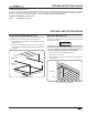
1. Prepare cutout and pre-drill screw holes (see illustration
below for dimensions).
2. Remove trim cover from control enclosure.
3. Position control enclosure into opening through the
backside.
4. Secure control enclosure to surface using screws
(not supplied).
5. Connect proper power source to the mounted remote
control enclosure.
6. Reinstall the trim cover. Seal the trim cover to the mounting
surface with silicone adhesive.
NOTE:Unitsareequippedwitha36″(914mm)flexibleconduit
connecting the control enclosure to the unit. Optional
conduitlengthsof6′(1829mm)and10′(3048mm)are
also available for digital temperature controller only.
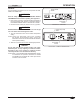
Power I/O (on/off) Switch
Both flush-style remote mounted control enclosures are
equipped with a Power I/O (on/off) switch. Move the Power
I/O (on/off) switch to the I (on) position to turn on the unit. The
indicator light in the switch glows when the unit is on.
Changing the Setpoint Temperature — Mechanical
Temperature Control
Turn the temperature control clockwise to increase the setpoint
temperature. Turn the temperature control counterclockwise to
decrease the setpoint temperature.
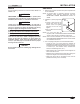
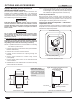
Thermostat Control
Power I/O (on/off) Switch
Mechanical Temperature Control
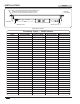
Remote Mounted Control Enclosure Installation Dimensions
Thermostat Enclosure
4″ (102 mm)
Digital Temperature Controller Enclosure
4-3/4″ (121 mm)
Mounting Surface
Trim Cover
Control Enclosure
Side View of Installed EnclosureFront View of Cutout
5-7/8″
(149 mm)
3-7/8″
(98 mm)
6-3/8″
(162 mm)
6-7/8″
(174 mm)
IMPORTANT NOTE:
Make sure the installation
location provides enough
room for electrical
connections to the control
enclosure.