
Service Manual, Diagrams and Assembling Charts
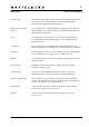
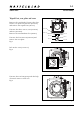
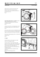
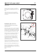
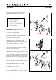
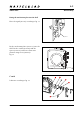
Table Of Contents

90308.EPS
001026
January 2001
903SWC
Reassembly
4:1
Revision 0
90308.EPS
001026
90311.EPS
001030
Lubricate the camera as detailed in the
appropriate lubrication chart. Use the
lubricants listed below:
= Isoflex Topas L32
= Isoflex PDP-48
= Loctite, e.g. Loctite 243
= Safety lacquer
Mechanism plate (30367-1)
Lubricate according to fig. 9.
Attach the spring (816702), the washer
(810542) and the spring (816751) to the
release mechanism (13337).
Mount the release mechanism to the
mechanism plate (30361-1) and place the
two springs according to Fig. 10 A.
Fit the bracket (12873) and the spring
(816709) into position and secure them
with the screw (822001).
Reassemble the driving gear (13343-1) and
the driving ratchet wheel (13340) according
to fig. 10 B and secure them with the screw
(825002). Make sure that the pawl and the
spring (816506) are in correct position (in
relation to the driving ratchet wheel).
Refit the signal release mechanism (13429)
and secure it with the screw (822031).
Fit the signal (20737) incl. the spring
(814705) to the catch (13427-1) and secure
it with the clip (817112).
Connect the spring (814705) to the bracket
(12873) and then fit the complete catch to
the mechanism plate.
Fig. 10
Fig. 9
A
B
816751
816702
13337
816751
816702
810542
12873
816709
822001
13340
816506
30361-1
13429
13427-1
20737
814705
817112
13343-1
825002
822031