
Service Manual, Diagrams and Assembling Charts
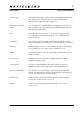
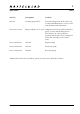
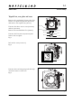
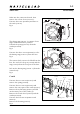
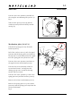
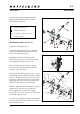
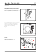
Table Of Contents

90308.EPS
001026
January 2001
903SWC
Disassembly
3:3
Revision 0
90307.EPS
001026
Fig. 7
Unscrew the screw (820047) and lift out
the complete mechanism plate (30367-1).
Fig. 7
Take out the spacer (810721) and the
washer (810928) from the shell (circular
area fig. 8).
Mechanism plate (30367-1)
Unhook the spring (814705) from the
bracket (12873).
Lift of the catch (13427-1) incl. the signal
(20737) and the spring (814705). Remove
the clip (817112) and disconnect the signal
incl. the spring (814705) from the catch.
Unscrew the screw (822031) and remove
the signal release mechanism (13429).
Unscrew the screw (825002), which is
secured with loctite, and separate the
driving gear (13343-1) and the driving
ratchet wheel (13340).
Unscrew the screw (822001), remove the
spring (816709) and the bracket (12873).
Remove the release mechanism (13337).
Remove the spring (816751), the washer
(810542) and the spring (816702) from the
release mechanism.
Fig. 8
Fig. 8
820047
30367-1
13337
816751
816702
810542
12873
816709
822001
13340
30361-1
13429
13427-1
20737
814705
817112
13343-1
810721
810928
825002
822031