
Service Manual, Diagrams and Assembling Charts
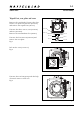
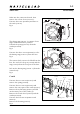
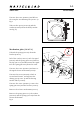
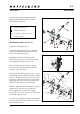
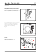
Table Of Contents

January 2001
903SWC
Disassembly
3:2
Revision 0
90304.EPS
001026
90305.EPS
001026
90306.EPS
001211
Make sure the camera is released, then
remove the release lever (13332-1).
Unscrew the screw (822002) and remove
the catch (21165).
Fig. 4
The driving ring (21081-1) consists of two
rings, mark their relative position.
Unhook the spring (814707) from the
washer (810928).
Fig. 5
Unscrew the three screws (820046) to free
the driving ring (21081-1) from the lens.
Fig. 4
The camera body can now be lifted from the
lens. Do not loose the gear (13320) and the
ring (13322) from the rear part of the lens!
Lift out the driving ring (21081-1) from the
camera body.
Fig. 5
Crank
Unscrew the two screws (821662) and
remove the spring (22328).
Unscrew the two screws (823640) and
remove the outer part of the crank (22331).
Remove the nylon string (22327) and lift
out the inner part of the crank (A).
Remove the tooth wheel (22335) and the
washer (810944).
Unscrew the four screws (820013 and
820015)
Remove the housing (22323).
Fig. 6
Fig. 4
Fig. 5
Fig. 6
21165
822002
13332-1
"Mark"
814707
810928
21081-1
13320
13322
821662
22328
823640
22331
22327
22335
810944
820013
820015
22323
A
820046