
Service Manual, Diagrams and Assembling Charts
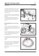
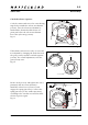
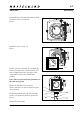
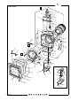
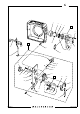
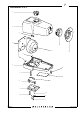
Table Of Contents

January 2001
903SWC
Reassembly
4:4
Revision 0
90309.EPS
001023
90304.EPS
001026
90312.EPS
010130
Fig. 17
Check the release sequence:
Cock the camera and move the outer driving
ring slowly towards the release mechanism
(13337). Free the release mechanism by
hand and the shutter should release at a
point just before the release mechanism
leaves the nylon stop (13295).
Fig. 17
If the shutter releases too early, or not at all,
it is adjusted by changing the mesh between
the gear (13320) and the toothed segment
(13346). For a small adjustment, turn the
gear (13320) 180º.
Fig. 18
Fit the catch (21165) and tighten the screw
(822002) and one screw (820046).
Install the release lever (13332-1) and
engage the spring (816709). Connect the
spring (814707) to the washer (810928)
according to the circular area and check the
release sequence again.
Fig. 19
21165
13332-1
816709
Fig. 18
Fig. 19
13346
13320
Lens
820046
822002
13337
13295