
Service Manual, Diagrams and Assembling Charts
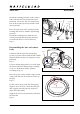
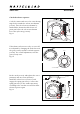
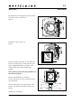
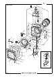
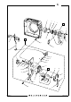
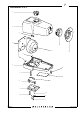
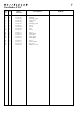
Table Of Contents

90306.EPS
001211
January 2001
903SWC
Reassembly
4:3
Revision 0
90309.EPS
001023
Fig. 14
821662
823640
22331
22327
22335
810944
820015
22323
22328
820013
Mount the housing (22323) on the camera
body with the four screws (820015) and
(820013). Check the axle so it turns freely.
Put on the washer (810944) and the tooth
wheel (22335).
Place the inner part of the crank (A) in the
housing and secure it with the nylon string
(22327).
Mount the crank (22321) with the two
screws (823640) and the spring (22328)
secured with the two screws 821662).
Fig. 14
Reassembling the lens and camera
body
Lubricate and then put the driving ring
(21081-1) in the camera with its index mark
aligned. Hold it in place by using two screws
(820046).
Fig. 15
If a new driving ring (21081-1) is used, align
the inner and outer driving rings according
to fig. 16. Mark their relative position
according to fig. 15.
Place the gear (13320) and the ring (13322)
on the lens and turn it clockwise to take up
the play.
Fig. 15
Fit the camera body, with the driving ring
aligned, on to the lens. Check that the gear
and coggsector mesh properly and press
down the body firmly.
Tighten the two screws (820046) and check
the function.
Fig. 15
A
Fig. 15
Fig. 16
"Mark"
814707
810928
21081-1
13320
13322
820046
Driving ring alignment
Axle