
Installation Guide


11
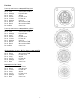
Pin Outs (continued)
Pump Communication Plug on DCP
Pin 1 Red +12V Can
Pin 2 Red +12V Power
Pin 3 Gray Shield
Pin 4 Green Comm Channel OH
Pin 5 Yellow Comm Channel OL
Pin 6 Blue Comm Channel IH
Pin 7 Orange Comm Channel IL
Pin 8 Black Can Ground
Pin 9 Black Power Ground
Pin 10 N/A
Pump Connection Colors
Pin 1 Black with Orange Stripe Pump 1 Ground
Pin 2 Black with Green Stripe Pump 2 Ground
Pin 3 Black with Yellow Stripe Shield Pump3 Ground
Pin 4 N/A
Pin 5 Orange with Black Stripe Pump 1 Positive
Pin 6 Green with Black Stripe Pump 2 Positive
Pin 7 Yellow with Black Stripe Pump 3 Positive
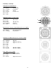
Flow Meter Connection on Pump Controller
Pin 1 White +5-12V Power
Pin 2 Green Ground
Pin 3 Brown Signal
Pin 4 Black Shield
Connector for Crop Eyes on DCP
Pin 1 Red +12V Power
Pin 2 Black Ground
Pin 3 White Signal
Pin 4 N/A