
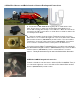
Installation Guide


10
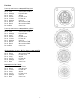
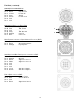
Pin Outs (continued)
006-6650VA to 006-6650LS2
Pin 1 Red Can Power
Pin 2 Black Can Ground
Pin 3 Yellow HT Can Hi
Pin 4 Gray Shield
Pin 5 Green HT Can Low
Pin 6 N/A
Pin 7 N/A
006-6650VA Harness to Baler Plug
Pin A N/A
Pin B Red TBC Power
Pin C N/A
Pin D Gray TBC Ground
Pin E Orange Can1 Hi
Pin F Blue Can1 Low
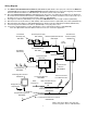
Main Power Connector on Dual Channel Processor (DCP)
Pin 1 Red +12V Power from tractor
Pin 2 Black Ground from tractor
Pin 3 Orange Keyed power
Star Wheel and Bale Rate Sensor connector on DCP
Pin 1 Blue +12V Power
Pin 2 Orange Ground
Pin 3 Black Signal for sensor 1
Pin 4 White Signal for sensor 2
Pin 5 N/A
Pin 6 N/A
Pin 7 N/A
Pin 8 Violet Star wheel input 1
Pin 9 Brown Star wheel input 2
End of Bale sensor on DCP
Pin 1 Brown Sensor Power
Pin 2 Blue Sensor Ground
Pin 3 N/A
Pin 4 Black Signal from Sensor
D
A