Installation Manual Model 664M Automatic Preservative Applicator 664M-14-INST 5/22 1
(intentionally blank) 2
Harvest Tec Model 664M Installation Table of Contents Introduction System Requirements Tools Needed Installation of Controls and Harnesses 1. Installation of Dual Channel Processor (DCP) DCP or PIP Location for AGCO Balers 2.
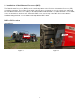
Introduction Thank you for purchasing a HayBoss G2 Model 696M Hay Preservative Applicator. This 696M applicator system has been designed to plug directly into the baler’s ISOBUS and display on a C1000 monitor. As well as the option of operation through an Apple iPad (not included) using the Hay App. The 696M Preservative Applicator System offers these advantages: 1. Operation coordinated with baler operation 2. Less cab clutter providing better visibility 3. Ease of use with all information on one screen 4.
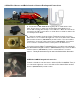
1. Installation of Dual Channel Processor (DCP) The Dual Channel Processor (DCP) has the same bolt pattern as the Precision Information Processor (PIP) you will be removing. The location of the main controller does not change so use the same holes and install the new Dual Channel Processor (DCP) in the same location with two 5/16” x 1” bolts, two 5/16” x 1-1/4” bolts, locks, fender washers and hex nuts.
2. Main Wire Harness and Baler Interface Harness Routing and Connections A. Route harness 006-6650LS2 along this path or similar inside of the baler. Keep harnesses away from moving parts and hydraulic hoses. Secure with existing cable clamps or use cable ties. When all connections are made to the DCP secure wires as shown above to allow for water to be shed away from the DCP. B. Under the chamber locate the Active Terminator from the end of the baler harness.
Installation of iPad Integration Control Locate a safe location in the cab of the tractor to place the iPad Integration Control (030-6672C). Recommended location is securely fastened out of the operators way in a location that is close enough to reach with the iPad cord. Connect the Power / Communication harness (006-6650TM(E)) to the bottom of the receiver.
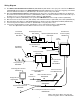
Wiring Diagram A. The Baler Power/Communication Harness (006-6650LS2) will attach to the open port of the Tractor Harness (006-6650TM) and run back to the Dual Channel Processor (006-6671LS). Connect the large plug of the Baler Power/Communication Harness (006-6650LS) to the bottom (shorter side) of the DCP. B. Attach the Baler Interface Harness (006-6650VA) in between the short whip cable hardwired to the DCP and the main Power/Communication Harness (006-6650LS2).
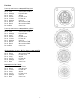
Pin Outs Power/Comm Harness 006-6650TM at Hitch Pin 1 Red +12V Power to TSD Pin 2 Red +12V Power to DCP Pin 3 Orange Keyed Power Pin 4 Gray Shield Pin 5 Green HT Can Low Pin 6 Yellow HT Can Hi Pin 7 Orange Can1 Hi Pin 8 Black Ground from TSD Pin 9 Black Ground from DCP Pin 10 Blue Can1 Low 2 3 iPad Integration Control / BLE on Harness 006-6650TM Pin 1 Red +12V Power from DCP Pin 2 Black Ground from TSD Pin 3 Yellow HT Can Low Pin 4 Gray Shield Pin 5 Green HT Can Hi Pin 6 Orange Can1 Hi Pin 7 Blue Can1 Lo
Pin Outs (continued) 006-6650VA to 006-6650LS2 Pin 1 Red Can Power Pin 2 Black Can Ground Pin 3 Yellow HT Can Hi Pin 4 Gray Shield Pin 5 Green HT Can Low Pin 6 N/A Pin 7 N/A 006-6650VA Harness to Baler Plug Pin A N/A Pin B Red TBC Power Pin C N/A Pin D Gray TBC Ground Pin E Orange Can1 Hi Pin F Blue Can1 Low A D Main Power Connector on Dual Channel Processor (DCP) Pin 1 Red +12V Power from tractor Pin 2 Black Ground from tractor Pin 3 Orange Keyed power Star Wheel and Bale Rate Sensor connector on DCP Pi
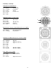
Pin Outs (continued) Pump Communication Plug on DCP Pin 1 Red +12V Can Pin 2 Red +12V Power Pin 3 Gray Shield Pin 4 Green Comm Channel OH Pin 5 Yellow Comm Channel OL Pin 6 Blue Comm Channel IH Pin 7 Orange Comm Channel IL Pin 8 Black Can Ground Pin 9 Black Power Ground Pin 10 N/A Pump Connection Colors Pin 1 Black with Orange Stripe Pin 2 Black with Green Stripe Pin 3 Black with Yellow Stripe Shield Pin 4 N/A Pin 5 Orange with Black Stripe Pin 6 Green with Black Stripe Pin 7 Yellow with Black Stripe Pump
Parts Breakdown (Converting a 500 Series to a 600 Series) 1 2 8 7 6 3 5 4 Ref 1 2 3 4 5 6 7 8 NP NP NP Description Terminating Resistor 500 Series-green DCP Main Control LS 600 Auto Dust Plugs-only one included Key Switch Wire-orange DCP Baler Harness 30” DCP Tractor Harness DCP Baler ISO/VT Harness iPad Integration Control Pre 2012 AGCO Integration Harness (not included) Optional ISOBUS Adapter Plug (not included) USB Cable 9 12 Part Number 001-5650Z 001-6671LS 006-5651PLUGS 006-5650K 006-6650LS2
Notes 13
Notes 14
Harvest Tec LLC. Warranty and Liability Agreement Harvest Tec, LLC. will repair or replace components that are found to be defective within 12 months from the date of manufacture. Under no circumstances does this warranty cover any components which in the opinion of Harvest Tec, LLC. have been subjected to negligent use, misuse, alteration, accident, or if repairs have been made with parts other than those manufactured and obtainable from Harvest Tec, LLC.
HARVEST TEC, INC. P.O. BOX 63 2821 HARVEY STREET HUDSON, WI 54016 PHONE: 715-386-9100 1-800-635-7468 FAX: 715-381-1792 Email: info@harvesttec.