
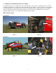
Installation Guide

9
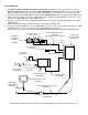
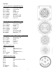
Pin Outs
Power/Comm Harness 006-6650TM at Hitch
Pin 1 Red +12V Power to TSD
Pin 2 Red +12V Power to DCP
Pin 3 Orange Keyed Power
Pin 4 Gray Shield
Pin 5 Green HT Can Low
Pin 6 Yellow HT Can Hi
Pin 7 Orange Can1 Hi
Pin 8 Black Ground from TSD
Pin 9 Black Ground from DCP
Pin 10 Blue Can1 Low
Power/Comm Harness 006-6650LS2 at Hitch
Pin 1 Red +12V Power to TSD
Pin 2 Red +12V Power to DCP
Pin 3 Orange Keyed Power
Pin 4 Gray Shield
Pin 5 Green HT Can Low
Pin 6 Yellow HT Can Hi
Pin 7 Orange Can1 Hi
Pin 8 Black Ground from TSD
Pin 9 Black Ground from DCP
Pin 10 Blue Can1 Low
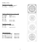
iPad Integration Control / BLE on Harness 006-6650TM
Pin 1 Red +12V Power from DCP
Pin 2 Black Ground from TSD
Pin 3 Yellow HT Can Low
Pin 4 Gray Shield
Pin 5 Green HT Can Hi
Pin 6 Orange Can1 Hi
Pin 7 Blue Can1 Low
ISOBUS Plug Baler Side
Pin 1 N/A
Pin 2 N/A
Pin 3 120 OHM with Pin 5
Pin 4 N/A
Pin 5 120 OHM with Pin 3
Pin 6 Orange Can1 Hi
Pin 7 Blue Can1 Low
ISOBUS Plug Tractor Side
Pin 1 N/A
Pin 2 N/A
Pin 3 +12V Keyed Tractor Power
Pin 4 N/A
Pin 5
Pin 6 N/A
Pin 7 N/A
Pin 8 Orange Can1 Hi
Pin 9 Blue Can1 Low
1
2
3
4
5
6
7
8
9
10
2
1
3
4
5
6
7