
Installation Guide


8
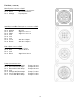
Wiring Diagram
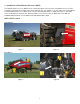
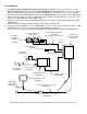
1. The Baler Power/Communication Harness (006-6650LS2) will attach to the open port of the Tractor
Harness (006-6650TM) and run back to the Dual Channel Processor (006-6671LS). Connect the large
plug of the Baler Power/Communication Harness (006-6650LS) to the bottom (shorter side) of the DCP.
2. Install green terminator (006-5650Z) to the port labeled Modular Port on the Pump Controller (006-5672).
3. Attach moisture and bale rate harness 006-7303H (Claas & Krone kits 006-7303HX) as well as the end of
bale harness (006-7400) to the DCP (006-6671LS).
4. Attach the Pump Control Harness (006-5650FM) between the Pump Controller (006-5672) and the DCP
(006-6671LS).
5. Connect the orange wires and attach the plug to the tractor’s ISOBUS port.
6. If using the optional ISOBUS connector (006-6670A) connect the end to the Communication Harness (006-
6650TM) in place of the iPad Integration Control (030-6672C) shown below.
7. Connect the orange keyed power wires (006-5650K) and attach the plug to the tractor’s ISOBUS port.
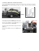
*Claas 3200-3400 balers will have star wheel assembly 030-4642 for mounting on side of bale chamber
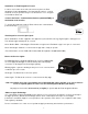
iPad Integration Control
030-6672C
Optional Port
Data
Transfer
Moisture/Bale Rate Harness
006-7303H
(006-7303HX – Claas & Krone)
Proximity Sensor (2X)
006-7303S
Star Wheel
Assembly (x2)
030-4641
or
030-4642
End of Bale Sensor
006-7400
Power/Comm Harness on Baler
006-6650LS2
Power/Comm Harness on Tractor
006-6650TM
Orange Wires
to Keyed Power
006-5650K
Terminating Resistor
006-5650Z
Pump Controller Harness
006-5650FM
Flow Meter
006-4725A
Pump Harness
006-4660Z
Pump Controller
006-5672
Dual Channel
Processor (DCP)
006-6671LS