
User Manual
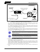

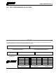

Table Of Contents
- 1 REGULATORY AND SAFETY INFORMATION
- 1.1 SAFETY SYMBOL CONVENTIONS
- 1.2 RF ENERGY EXPOSURE AWARENESS AND CONTROL INFORMATION FOR FCC OCCUPATIONAL USE REQUIREMENTS
- 1.3 COMPLIANCE WITH RF EXPOSURE STANDARDS
- 1.4 REGULATORY APPROVALS
- OCCUPATIONAL SAFETY GUIDELINES AND SAFETY TRAINING INFORMATION
- 1.6 COMMON HAZARDS
- 1.7 SAFE DRIVING RECOMMENDATIONS
- 1.8 OPERATING RULES AND REGULATIONS
- 1.9 OPERATING TIPS
- 2 SPECIFICATIONS
- 3 INTRODUCTION
- 4 UNPACKING AND CHECKING THE EQUIPMENT
- 5 PLANNING THE INSTALLATION
- 6 ANTENNA INSTALLATION
- 6.1 ANTENNA MOUNTING LOCATIONS
- 6.2 ANTENNA INSTALLATION PROCEDURES
- 7 FRONT-MOUNT RADIO INSTALLATION
- 8 REMOTE-MOUNT RADIO INSTALLATION
- 8.1 MOUNTING THE REMOTE-MOUNT RADIO
- 8.2 REMOTE-MOUNT RADIO’S DC POWER INSTALLATION
- 8.3 CONTROL HEAD INSTALLATION
- 8.3.1 General Information on the CH100 Control Head
- 8.3.2 General Information on the CH721 Control Head
- 8.3.3 Multi-Head Radio Installations
- 8.3.4 Control Head Mechanical Installation
- 8.3.5 Control Head-to-Radio CAN Cable Connections
- 8.3.6 Control Head Power Cable Installation
- 8.3.7 Using Vehicle Fuse and TTap Kit (Optional) Instead of Waterproof Inline Fuse Holder (Standard)
- 9 SPEAKER INSTALLATION
- 10 MICROPHONE ATTACHMENT
- 11 OPTIONAL CABLES AND CONNECTIONS
- 12 GPS NMEA-FORMATTED DATA CONNECTION
- 13 INITIAL POWER-UP TEST
- 14 PERFORMANCE TESTS
- 15 COMPLETE THE INSTALLATION
- 16 WARRANTY REGISTRATION
- 17 WARRANTY

14221-1200-4000, Rev. A
83
10. Compare the wattmeter reading with the RF power output range of 15 watts or less. This limit exists
because the multi-band (untuned) antenna has a VSWR of ≤3:1.
Transmit only for as long as needed to take the measurement, then immediately disable
the transmission.
11. If the wattmeter reading is within the range, record the value in the appropriate space on the data
collection form near the end of this manual.
If the wattmeter reading is outside the range, make sure the antenna is consistent with the specified
frequency range of the radio. Recheck all antenna connections, and measure the reverse power again.
If these checks/corrections fail to produce a reading within the range, replace the antenna and repeat
the entire antenna test procedure. Any value exceeding the maximum allowable reflected power value
will result in a diminished RF output signal. If problems persist, contact the Technical Assistance
Center (see page 21).
12. Repeat on test channels within the other RF bands, until at least one channel in all bands has been
tested.
13. Disconnect the coaxial cable jumper and wattmeter.
14. Permanently connect the cable from the vehicle-mounted antenna to the radio’s antenna cable by
mating the two TNC connectors together. Use two pairs of soft-jaw pliers to gently tighten this
connection. Do not over tighten and do not twist either cable.
15. Make several test calls on the radio system to verify operation of the mobile radio. Before making the
calls, select other talk groups or conventional channels, as required to verify operation.
To prevent RF leakage and ensure peak performance, make sure the RF connectors are
tight, but do not over-tighten so connector damage will not occur.
Improper installation of the RF cables may lead not only to poor radio
performance but also to harmful exposure to RF electromagnetic energy.
Testing is complete. The radio is now ready for normal communications.
NOTE
NOTE
WARNING