
User Manual
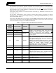
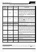
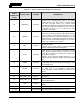
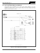
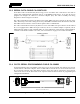
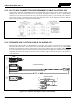
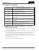
Table Of Contents
- 1 REGULATORY AND SAFETY INFORMATION
- 1.1 SAFETY SYMBOL CONVENTIONS
- 1.2 RF ENERGY EXPOSURE AWARENESS AND CONTROL INFORMATION FOR FCC OCCUPATIONAL USE REQUIREMENTS
- 1.3 COMPLIANCE WITH RF EXPOSURE STANDARDS
- 1.4 REGULATORY APPROVALS
- OCCUPATIONAL SAFETY GUIDELINES AND SAFETY TRAINING INFORMATION
- 1.6 COMMON HAZARDS
- 1.7 SAFE DRIVING RECOMMENDATIONS
- 1.8 OPERATING RULES AND REGULATIONS
- 1.9 OPERATING TIPS
- 2 SPECIFICATIONS
- 3 INTRODUCTION
- 4 UNPACKING AND CHECKING THE EQUIPMENT
- 5 PLANNING THE INSTALLATION
- 6 ANTENNA INSTALLATION
- 6.1 ANTENNA MOUNTING LOCATIONS
- 6.2 ANTENNA INSTALLATION PROCEDURES
- 7 FRONT-MOUNT RADIO INSTALLATION
- 8 REMOTE-MOUNT RADIO INSTALLATION
- 8.1 MOUNTING THE REMOTE-MOUNT RADIO
- 8.2 REMOTE-MOUNT RADIO’S DC POWER INSTALLATION
- 8.3 CONTROL HEAD INSTALLATION
- 8.3.1 General Information on the CH100 Control Head
- 8.3.2 General Information on the CH721 Control Head
- 8.3.3 Multi-Head Radio Installations
- 8.3.4 Control Head Mechanical Installation
- 8.3.5 Control Head-to-Radio CAN Cable Connections
- 8.3.6 Control Head Power Cable Installation
- 8.3.7 Using Vehicle Fuse and TTap Kit (Optional) Instead of Waterproof Inline Fuse Holder (Standard)
- 9 SPEAKER INSTALLATION
- 10 MICROPHONE ATTACHMENT
- 11 OPTIONAL CABLES AND CONNECTIONS
- 12 GPS NMEA-FORMATTED DATA CONNECTION
- 13 INITIAL POWER-UP TEST
- 14 PERFORMANCE TESTS
- 15 COMPLETE THE INSTALLATION
- 16 WARRANTY REGISTRATION
- 17 WARRANTY

14221-1200-4000, Rev. A
80
14.1 REQUIRED TEST EQUIPMENT
Table 14-1: Required Test Equipment
TEST EQUIPMENT MODEL / PART NUMBER & DESCRIPTION
Peak-Reading
Wattmeter
Bird Electronic Corp. Model 4314B (or equivalent) with Type
N female
connectors at input and output ports.
Wattmeter
Slug
Bird Electronic Corp. Element 50C or 100C (50 or 100-Watt max. respectively),
100 - 250 MHz frequency range (or equivalent).
Wattmeter
Slug
Bird Electronic Corp. Element 50E (50-Watt max.), 400 - 1000 MHz frequency
range (or equivalent).
RF Coaxial
Jumper Cable
Pasternack Enterprises PE3661-36 (or equivalent) 50-Ohm Coaxial Cable
with TNC male connector and Type N male connector, approximately three
(3) feet in length. The utilized cable must have VSWR below 1.5:1 within
the RF passband.
N-to-TNC
RF Adapter
Pasternack Enterprises PE9090 (or equivalent) Type N male to TNC female
adapter. Required to connect the cable of the vehicle-mounted antenna to
the wattmeter.
50-Ohm RF Terminator
(“Dummy Load”)
Pasternack Enterprises PE6106 (or equivalent) 50-ohm RF terminator rated
at greater than 50 watts power, with Type N male connector.
Vehicle-Mounted
Antenna
Tests are performed with the vehicle-mounted antenna per the installation
described in Section 6 of this manual.
14.2 TRANSMITTING INTO A 50-OHM RF TERMINATOR—TESTING THE
RADIO’S RF OUTPUT POWER
1. Using the Type N male to TNC male RF coaxial jumper cable, connect the radio’s antenna connector
to the wattmeter’s input connector. Refer to Figure 14-1 as necessary.
2. Connect the 50-ohm dummy load to the wattmeter’s output connector, in place of the antenna cable
from the vehicle-mounted antenna.
3. Turn the radio on and set it to a VHF P25 conventional channel allocated for radio testing. This same
channel should be used during the antenna test procedures presented in the subsequent section.
4. Position the wattmeter’s slug to measure forward RF output power. Rotate it if necessary. The arrow
on the face of the slug must point away from the radio and towards the dummy load for forward
power measurements.
5. Set the wattmeter to measure peak RF power.
6. Key the radio’s transmitter via the microphone’s PTT button.